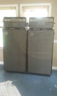
The stuff the LOUD guy said about 'power hungry" etc is so much smoke and mirrors. The standard SVT will work over a much wider range of voltage, and the SVT-CL will also.
The effect of lower voltage is to reduce all power supply voltages, and reduce the bias, as well as the filament voltage. These are more-or-less self-correcting, over a sensible range of voltages.
It's pretty obvious that there is a serious problem with the voltage sensing in the VR. I don't actually know exactly what it is in detail, but I can definitely suggest how to get around it.
It seems that the relay circuit is the culprit. The relay makes contact between J26, and the J27/J28 pair. These are "faston" tabs on the AC connection PC board. J 26 is the return from the standby switch, and J27/28 are for the main power transformer.
The relay is inserted between the standby switch and the power transformer. If either one is open, you get no high voltage, and so no power out.
There is a timing circuit on the power amp board. It forces a delay after the filaments come on, before the relay will close and "enable" the standby switch, allowing high voltage to be applied to the tubes.
But, none of the "protection" circuitry from the SVT-CL is present. So the only function of the relay is to provide a delay after the filament power is applied. Until the delay is finished, you won't have power applied, even if the standby switch is set to provide it.
And, of course, if the unit "decides" that the voltage is too low during the show, it will kill the high voltage and shut you off. Not good.
Therefore, if you can manage to wait a bit before switching from standby to "power on" mode, there isn't any particularly good reason why you can't just solder a piece of heavy wire across the relay contacts, totally bypassing it. Then YOU decide when it is in standby, or not.
Other methods involving a 2 into 1 faston tab might also work, although there is limited room for any extra parts inside.
And anyone from outside the US and using 230V/240V will be using only one of the J27/28 pair, and can probably just move the wire from J26 over to whichever of J27/28 is not used. That does the same thing.
unfortunately, for 120V , both are used, so that simple method won't work directly. With a "2 into 1" faston adapter, it could.
If you just can't stand it, probably there are different resistor values that can be found to widen the voltage range of the relay drive circuit. I don't see a particularly good reason to bother. Without extreme low voltage, the amp should work regardless...... Old SVTs, the original SLM SVT-HD, SVT-II, and years of SVT-CLs have worked fine since 1969, and there isn't a good reason for the CVT-VR to be different.
In fact, that is a good point, I never have gotten a good reason why the VR had to have the fancy extras....... as usual, one of them is the cause of the major problem in the unit...... They would have been better left off, to make the unit a fairly direct re-issue.
As it is, the VR has a different filament transformer than some earlier SLM SVTs, and it is different from the original. The 6.3 volt winding is the same, but there are additional windings which are not present on earlier units. These are, in part, for the preamp DC filaments of the VR. Another "nice feature", but not really required.........