• TalkBass has been independent since 1998. Add your voice.
    Create a free account to reply to discussions, view embedded media, and browse with fewer display ads.
    Join freeLog in
    Want zero display ads or expanded classifieds tools? Compare plans.

Ampeg V-4B - Blown cathode Resistors

Hi,

About three months ago I repaired an Ampeg V-4B reissue that had very low volume.

I tested the old tubes with a Hickok 600, and all of them were weak. The amp came from a rehearsal room, so it had probably been working hard.

I installed a new set of tubes, set the bias, and the amp sounded great.

About a week ago, the owner told me that there was a 100 Hz hum/noise that started after the amp was taken out of standby.

My first thought was that the filter caps might have gone bad.

Yesterday, before bringing the amp back to me, the owner powered it up and it immediately started smoking.

Today I received the amp and found that one of the 10Ω cathode resistors had completely burned, while another one had drifted up to around 1kΩ.

I can't find the schematic for this version of the V-4B reissue with the cathode resistors R12, R13, R14 and R15.

Does anyone have this schematic and could send me a copy?

Today, I retested the four output tubes on the Hickok 600 and all of them tested good.

I measured the bias voltage on pin 5 of all four 6L6s, with the tubes removed, and I get -43.5 V on each socket.

All the screen resistors test good.

In this situation, what could have caused those two cathode resistors to burn?

 
When a 10 ohm cathode resistor fails like that, it's usually due to a gross fault… either a screen to grid short or a loss of bias. The tube that fails can cause the opposite pair to draw a lot more current and also fail. The fault can be intermittent too.
 
When a 10 ohm cathode resistor fails like that, it's usually due to a gross fault… either a screen to grid short or a loss of bias. The tube that fails can cause the opposite pair to draw a lot more current and also fail. The fault can be intermittent too.
Thanks, that makes sense.

The possibility of an intermittent fault is a good point. I tested all four output tubes on a Hickok 600 and they all tested good, but of course that doesn't necessarily rule out a fault that only appears at full operating voltage and temperature.

Given the symptoms and the burned cathode resistors, what checks would you recommend performing at this point before powering the amp up again? Is there anything in particular you would focus on first?
 
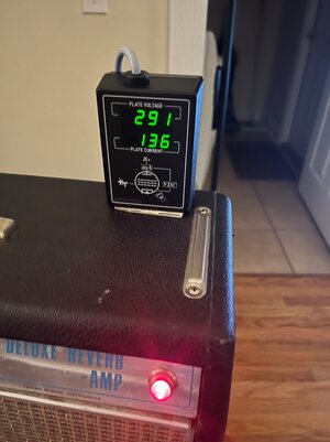
I recently had red plating on my '69 Deluxe Reverb. I read a plate voltage of ~300 volts and 100ma plate current on the original 6V6 and new replacement power tubes. I checked the bias caps and resistors and they were all good. It turned out to be a bad solder at the resistor that connects to the power transformer lead. This was an intermittent problem for a little while until I discovered it. It pays to look and poke around a bit.
 

Attachments

  • IMG_7212.jpeg
    IMG_7212.jpeg
    1.2 MB · Views: 9
  • IMG_7211.jpeg
    IMG_7211.jpeg
    1.1 MB · Views: 8
  • IMG_7253.jpeg
    IMG_7253.jpeg
    936 KB · Views: 9
  • IMG_7258.jpeg
    IMG_7258.jpeg
    903.9 KB · Views: 10
  • IMG_7251.jpeg
    IMG_7251.jpeg
    1.6 MB · Views: 9
Thanks, that makes sense.

The possibility of an intermittent fault is a good point. I tested all four output tubes on a Hickok 600 and they all tested good, but of course that doesn't necessarily rule out a fault that only appears at full operating voltage and temperature.

Given the symptoms and the burned cathode resistors, what checks would you recommend performing at this point before powering the amp up again? Is there anything in particular you would focus on first?
It could be anything.
 
Note that the cathode resistors are 10 ohm 1W, don't use a higher wattage rating. It is intended that they blow in the event of a problem. It wouldn't hurt to check D1, D2, D3, and D4, the 1N4007 flyback diodes. The tubes may have tested good but inspect the sockets for cracked or bad solder joints, etc.

Ampeg posted this bias procedure on TB. Check the bias with the 6L6GC tubes installed.


V4BR BIAS INSTRUCTION:
1. CONNECT LOAD TO AMPLIFIER {this can be a speaker cabinet or a dummy load}
2. TURN R16 (BIAS ADJUSTMENT POT) FULLY CCW (MINIMUM SETTING)
3. TURN MASTER CONTROL FULLY CW
4. TURN POWER SWITCH TO ON AND WAIT 2 MINUTES
5. TURN STANDBY SWITCH ON
6. ENSURE THERE IS NOTHING PLUGGED INTO INPUT CHANNELS
7. WAIT 10 MINUTES {I like to wait 30 minutes}
8. MEASURE VDC ACROSS R12, THE CATHODE RESISTOR OF V5
9. ADJUST R16 UNTIL YOU MEASURE 450mVDC ACROSS R12
10. MEASURE VDC ACROSS R13 (V6). SHOULD FALL BETWEEN 400mVDC - 500mVDC
11. REPEAT STEP #10 FOR R14 (V8), THEN R15 (V7)
12. ALL MEASUREMENTS FOR V5, V6, V8, AND V7 SHOULD BE WITHIN 400mVDC -500mVDC
12A)
IF #12 IS TRUE, ENJOY 100W OF V-4B


IF #12 IS FALSE, THE TUBES ARE NOT PROPERLY MATCHED FOR YOUR PRECIOUS V-4B, SO GET NEW ONES.
 
  • Like
Reactions: bass player 53