• TalkBass has been independent since 1998. Add your voice.
    Create a free account to reply to discussions, view embedded media, and browse with fewer display ads.
    Join freeLog in
    Want zero display ads or expanded classifieds tools? Compare plans.

Baltic birch semi-hollow Jaguar

So no one played the "what's wrong with the jig" question in a previous post. I spent some time cutting down the saddle which was sold as 1/8" thick to 1/8" thick (maybe they want to sell their saddle sanding jigs). Here's how it sits in the bridge:
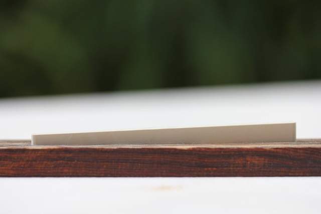
bridge+saddle_small.jpg


The problem is the guy in the video makes his bridge without compensation at all; the saddle just sits parallel to the edges of the bridge. Because there are two angles going on with my jig - one for the 7 degree back tilt and another for the 6 degree intonation compensation - the slot cuts 2mm deeper at one end.

There's plenty of material below the top surface of the bridge even at the shallow end so I think I'm going to just cut the top to compensate unless someone has a better idea...
 
  • Like
Reactions: ctmullins
Because the piezo element will raise the level of the saddle I wanted to check by how much. So I needed to mount the electronics as it will be once the instrument is done. I mounted the string-through ferrules as well which will sit recessed below the "back" of the bass. I'll need to make a cover too in order to access the battery, preamp and wiring should service be necessary.

electronics_small.jpg


The cable from the preamp has to thread through the hole in the body, then through the hole in the top where it goes to the bridge.

piezo_wire_bridge_small.jpg
 
  • Like
Reactions: Jisch
Very clean work. I tried to figure out the jig riddle, but I’m apparently not smart enough. :roflmao:

Good repair on the body edge too!
 
  • Like
Reactions: mnats
As far as cutting the rounded bottom, if you don't get a ball end mill (or ball end router bit) to deal with that, you can grind yourself a scraper from something that has the radius you need and scrape it in by hand - a bit slower, but less special-purpose tooling to buy.

$10-13 at McMaster if you have an 1/8" collet (I'm assuming you need 1/8" round since you have 1/8" bridge thickness.)

McMaster-Carr
 
  • Like
Reactions: mnats
Don't trust myself to do the rounding by hand with enough precision but I will look into that ball end mill if I try this again. For now the slot is already too deep. Strung it up with the Jazz neck and found the E string was too low. Not sure if I should drop the neck route or not.

test_small.jpg


The bridge will also have to sit further back than where I had it initially placed so I'll have to slot that piezo cable hole to allow for adjustment. It seems to stay where it's told to without anything to secure it other than string pressure but I've seen one that has slots and screws so I may take that route before shaping the bridge. Nice thing is the body shape is so wonky that visually it doesn't seem to matter if the bridge isn't perfectly perpendicular to the string line.
 
If there are to be mag pickups, their depth (and mounting) would be a controlling factor on routing the neck deeper - if none, then...

Another possibility would be to shim the bottom of the slot under the piezo, perhaps even with something epoxied in place and then recut it a bit shallower.
 
  • Like
Reactions: mnats
I had allowed for magnetic pickups but now that I've heard piezo I might be willing to commit to that only. It might also give me the opportunity to try that weakening thing that Bruce does to see if there is an audible (to me) difference.

Thanks for your suggestion - it got me thinking. I have some casting epoxy that is very thin when mixed but extremely hard when set - which takes forever. If I put the bridge back on that ramp part of the routing jig but rotate it 180 degrees then epoxy poured into it should set level with the top surface of the bridge. Maybe there is enough surface tension to make a slight curve too which would put it closer to the shape suggested by Rick Turner...

*edit* So I got excited about this idea and mixed up some epoxy:

epoxycast_small.jpg


...stuck it in a sacrificial squeeze bottle with needle:

glue_bottle_epoxy_small.jpg


Then used a poor man's vacuum chamber to reduce the number of bubbles and help it flow in the channel. The bridge is now rotated so the 7 degree back tilt is going the other way, negating the drop over that span WRT gravity.

heat_tip_small.jpg


There's a nice, shiny, concavity running along the length now that should cradle that piezo element nicely. Now if I can wait a week while the epoxy sets...

epoxy_curvature_small.jpg


Thanks @T_Bone_TL for pointing me in the direction of filling that channel!
 
Last edited:
At this rate I should qualify for the dunce of the year award. Of course rotating the bridge on that ramp just made the slot angle go in the opposite direction.

bass_side_saddle_slot_small.jpg
treble_side_saddle_slot_small.jpg


Will re-pour another layer with the bridge level while the epoxy is still a little soft...
 
While I wait for the second layer of epoxy to cure in the bridge slot I decided to work on the neck. I forgot to mention at the start of this exercise that the thing that influenced my decision to make a piezo fretless was this video. Originally it was linked from another forum here. It could just be context or the way they were recorded but it surprised me how many instruments that I would never consider owning sounded surprisingly good. The piezo fretlesses were a standout.

At different times I had purchased both a slotted and radiused and unslotted fingerboards from StewMac.

slotted_unslotted_top_small.jpg


Since this one is going to be a medium scale lined fretless I still need slots. I figured that the existing 34" scale finger board would make a good template, so I put a few pieces of carpet tape on it and aligned the center of the 1st fret with the nut slot I'd cut in the unslotted board.

slotted_unslotted_small.jpg


If my calculations are correct it should give me a 32.088" scale.

I made a new X-ACTO blade indexing jig to fit atop the low fence of the crosscut table.

crosscut_jig_indexing_small.jpg


Surprisingly, it was all about the right height to fit the two back to back fingerboards, although the X-ACTO blade was an incredibly tight fit on the pre-slotted board (while almost too loose on my own slots cut with the new StewMac blade).

new_fingerboard_small.jpg


Like a car race it's probably more fun to watch someone fail. There should be ample opportunity for that as I continue working on the neck.
 
Not so much "more fun"(we do feel your pain), but everybody learns a lot from sharing the screw-ups and the fixes for the screw ups, while the "perfect falling dominos nothing goes wrong" builds are nice, they are less helpful to the vast majority of us who screw up from time to time. Getting out of the screw-up without "toss it in the chipper and start over from scratch" (literally how the "wood products" company in the next town to where I grew up handled things, from what I heard from folks who worked there) is often where some really creative work gets done.
 
  • Like
Reactions: chinjazz and mnats
After two layers of epoxy in the bridge slot there was barely 1/4 of the total saddle height in the bridge even before putting the piezo in. Luckily, I'd used that jig to cut the slot so it was just a matter of hogging out the epoxy to get back to where I'd begun:

routing_epoxy_small.jpg


I made a trip down to the woodworker's supply and picked up some Titebond Original, some West System epoxy and both the fast and slow hardener. I bought the pumps too, but discovered that the volume it dispenses is too great for most of my purposes.

I mixed a batch with slow hardener excess from priming the pump in my usual plastic shot glass that I've always used with the casting epoxy:

west_system_mixed_small.jpg


Same as before I put it in one of the small squeeze bottles and laid a bead down the bottom of the saddle slot:

west_system_new_layer_small.jpg


Went up and made a batch of soup for the week, then went down to do something else when I noticed something interesting:

west_system_shot_plastic_small.jpg


Seemed as though it must have gotten a little hot in the pot! Already the mix seemed to have cured fairly well and was quite hard to the touch. The casting epoxy would have been still very soft a number of hours after mixing...

Luckily I checked the bridge as well and found that the formerly closed hole that I'd drilled for the piezo cable that was filled with cured epoxy was not as watertight as I'd thought. A small pool had formed under the bridge on my poly coated MDF work surface.

Here's the strange part though - that epoxy, thank goodness, was still quite syrupy and I was able to use thinner to remove it from the bridge and bench top. I sealed the bottom of the bridge with some kapton tape and left it to set.

Any theories as to why it had not set hard like the stuff in the cup?
 

Attachments

  • epoxy_dust_small.jpg
    epoxy_dust_small.jpg
    21.2 KB · Views: 34
Self-heating.

A thin layer will cure as expected. A cupful will self heat (exothermic reaction) and the fast stuff will even melt the cup. The bigger the cup, the greater the heat - the self heating speeds the cure and that makes more heat...

You can offset this somewhat by literally keeping it on ice, or by mixing much closer to "only as much as you are applying" (and it's unfortunate that you missed some past discussion of the often excessive amount the pumps involve.) Likewise, you can alter how slow the slow stuff cures (even in thin layers) by heating the work up (generally after applying the epoxy.)
 
  • Like
Reactions: mnats
Self-heating.
In spite of all of the evidence in front of me I somehow missed the fact that the larger volume of epoxy in the platic cup created more heat than the thin layer in the bridge slot. Thanks for your input.

It seems as though the slowly escaping liquid from the tiny hole in the bridge caused that end to sink lower than the other. So I had to put another layer in yet again to even it up.

I missed the earlier discussion about pumps but have done a few searches subesequently. Even if not using them for metering out the correct amounts I like the convenience of not having to open a screw top then wiping down the bottle threads as I've done with the casting epoxy. I always use a small scale to get the proportions right. But I've taken note of Bruce's comments about the hardener's shelf life and exposure to air. My casting epoxy seems to suffer no ill effects of that sort.
 
The "blue pole" truss rod has a hex adjustment enclosed in a long, thick tube. When laying out the rout I realized that I'd need to drill a hole in the end of the neck to accommodate this adjustment sleeve. In the past my hand held drilling technique was often such that any hole that was supposed to be straight would be angled awkardly. But I saw an episode of Holmes on Homes once - I think his daughter was demonstrating how to drill a straight hole by keeping your eye on the opposite end of the drill as well as the business end.

So my technique has improved thanks to that tip but not so much that I trust drilling a straight hole through the end of an expensive maple neck blank. I did a few searches and mostly found jigs that use metal sleeves to guide a long bit similar to what's shown in Hiscock's book. It was hard enough finding a bit that was the correct size let alone something very long:

drill_23-64ths_small.jpg


A long time ago I bought one of those cheap drill presses that in spite of its low cost has never skipped a beat. Problem with a small bench mounted unit is that its base gets in the way of mounting something vertically. So I removed the base and screwed it into one of my work benches near the edge:

bench_mount_drill_press_small.jpg


Making sure the cast housing was plumb I turned the table 90 degrees so I could attach the neck blank to it. Then I used a spirit level to put a test piece in:

test_piece_small.jpg


Cut it open to confirm that it was drilling straight:

test_drill_cross_section_small.jpg


Lined up the piece of maple and made the hole:

finished_hole_small.jpg


Probably doing it in some overly-complicated way but I'm happy that the bit did not come crashing through the top surface of my neck like it would have done if I'd used my cordless drill.
 

Attachments

  • drill_depth_small.jpg
    drill_depth_small.jpg
    19.9 KB · Views: 35
  • hole_depth_two_small.jpg
    hole_depth_two_small.jpg
    20.5 KB · Views: 33
  • drilling_small.jpg
    drilling_small.jpg
    16.2 KB · Views: 36
  • hole_depth_small.jpg
    hole_depth_small.jpg
    18.4 KB · Views: 35
  • drill_alignment_maple_small.jpg
    drill_alignment_maple_small.jpg
    17.9 KB · Views: 32
  • test_drill_alignment_small.jpg
    test_drill_alignment_small.jpg
    28 KB · Views: 31
Re: the neck pocket epoxy mold- I saw a video awhile back (I’ll link if I find it) in which the neck pocket is just rough cut with a jigsaw, and he used BONDO then fit the taped up heel of the neck into the joint. He uses this template to clone with a router onto mdf or whatever permanent template material you prefer. Worked like a charm to clone a fender pocket for me
 
Re: the neck pocket epoxy mold- I saw a video awhile back (I’ll link if I find it) in which the neck pocket is just rough cut with a jigsaw, and he used BONDO then fit the taped up heel of the neck into the joint. He uses this template to clone with a router onto mdf or whatever permanent template material you prefer. Worked like a charm to clone a fender pocket for me
I have no doubt that Bondo would work better than the casting epoxy I tried. In terms of viscosity they are on opposite ends of the spectrum. In terms of odor they are also on opposite ends!
 
  • Like
Reactions: eddododo
Recent progress has mostly centered around building a table for my new 1/2" router so I can continue with the truss rod route. I mostly work outside since my workshop serves various hobbies including photography - wood dust doesn't play nicely with taking pictures. But sometimes the weather doesn't cooperate so I decided to build the table under an existing deck. It attaches to a brick wall using a French cleat (no jokes please).

french_cleat_small.jpg


router_table_unfinished_small.jpg


router_table_insert_small.jpg


That aluminum insert came from Ebay. There are plenty of sellers with similar products but few that provide dimensions. If they do, they are usually just the gross dimensions of the perimeter. It was a gamble because I needed the router mounting holes on 85mm centers. It arrived with holes in 95mm spacing that appeared to be cast in place. On the underside were a number of alternate hole spacing cast into the base. Because the 85mm ones were so close to the existing holes, I used some JB Weld to fill them, then used the router itself to smooth the top again, then drilled and countersunk the 85mm holes.

On the bass itself, I couldn't test the E string because it kept buzzing so badly. I found my neck route was a little too shallow but even after fixing that the problem remained. Finally I figured out that the body through design - made so that I could fit 34" scale strings on what will be a medium scale bass - allowed the test strings to sit at the nut such that it was sitting on the narrow part of the string. That caused the string to buzz at the first fret of the 34" scale test neck. Sometimes I really have to wonder if I'm starting to lose it.

Initial tests of the DTAR pickup showed that the G and E string's volume was much lower than the other strings. I thought maybe it was because the last 1/8" of the piezo is inactive. Also, the cable end was getting stuck in the too-small hole. So I drilled an 1/8" into the dead end and drilled out the cable end under the bridge with no change.

saddle_slot_dead_end_small.jpg


bridge_piezo_bottom_small.jpg


It finally dawned on me is that I spent too much time worrying about the saddle being too loose in the slot rather than the other instruction that it must "slide into the slot smoothly and with very little resistance." I did some sanding of the sides and one rounded end until it did just that. Now the balance between the strings is good.

The mechanics seem so obvious when you think about it a little. The saddle vibrates due to the strings while the bridge is fixed to the body. The piezo sits between them. Unless there is a difference in the motion between them you may as well be waving the piezo in the air or fixing it to the body alone.

I also did a control cover cut-out for the back of the bass:

control_cover_cutout_small.jpg
 

Attachments

  • blue_pole_small.jpg
    blue_pole_small.jpg
    12.7 KB · Views: 27
Last edited:
My limited free time has been spent working on the router table and getting the bridge assembly in shape. Eventually the two efforts would converge in a spectacular disaster.

The good news is that I cut a cove at the bottom of the Micarta saddle to match the round piezo element as suggested in the advanced installation instructions that come with the DTAR. I used a small rat-tail file. The sound improved immensely - I was impressed with the degree of improvement.

saddle_cove_cut_small.jpg


I added some slots to attach screws through the bridge to threaded inserts in the body as intonation adjustment. I stole the idea from Link Removed.

bridge_adjustment_mounted_small.jpg


Looking at the shape of the chambering and particularly at the narrow area below the neck mount I was not too sanguine at the idea of routing "weakening" slots. Eyeballing it, I think about three slots would fit in the narrow area between the neck and bridge. Between the improved sound of the saddle modification and the lack of area to weaken I may have to skip this experiment.

jaguar_layer_one_small.jpg


Finally, I wanted to refine the shape of the bridge so I put the tall bit that came with the new router in and mounted the assembly on the new router table. Carefully adjusting the fence so that a hair's width of material would come off at a time, I tentatively fed the bridge into the bit. It appeared to be going smoothly until it caught the bit in just the right way to tear a chunk out of the end. Thinking I may have been feeding it in the wrong way I tried the opposite side only to have it rip the bridge from my fingers and skitter across the top.

bridge_damage_small.jpg


Given the work that went into getting that slot and saddle right I'm determined to save it.
 

Attachments

  • bridge_intonation_adjustment_slot_small.jpg
    bridge_intonation_adjustment_slot_small.jpg
    80.4 KB · Views: 33
Using a rotary file in the drill press with a cross slide vice I was able to get a shape close to what I had envisioned for the bridge. I still can't get over how much better it sounds after the coving of the saddle.

jaguar_bridge_repaired_small.jpg


Probably the wrong place to ask but there are some clever minds here and not too much "noise". I noticed that the residual hum of the pickup/preamp system reduces significantly when you touch the end pin jack. Given that I'll be using nylon coated flat wound strings, what would be a good, unobtrusive way to get body contact to the preamp's ground? I don't tend to anchor my thumb on the body when I play so a metal pad there is out.