• TalkBass has been independent since 1998. Add your voice.
    Create a free account to reply to discussions, view embedded media, and browse with fewer display ads.
    Join freeLog in
    Want zero display ads or expanded classifieds tools? Compare plans.

Baltic birch semi-hollow Jaguar

Seems as though my suspicions were correct, though I was still surprised to see this. On the left is the partially disassembled DTAR piezo pickup while on the right is the Mighty Mite.
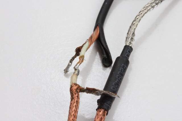
dtar_piezo_cable_mighty_mite_cable_small.jpg


The DTAR uses a spiral wound shielded cable while the Mighty Mite uses a braided shield. So far, all of the EBay purchased piezo elements have used nothing but braided shielded cable. I’m not sure why this spiral wound stuff was used on the DTAR. It makes a mockery of the internally mounted preamp used ostensibly to reduce noise. *edit: This spiral wound shielding has gaps in the coverage possibly due to issues in construction such as pulling on the shield while stripping. I do not mean to imply that all spiral wound shielded cable is inferior.

I employed the same construction at the junction but used a length of braided cable cut from one of the other pickups to splice onto the DTAR piezo. It's clever - the inner conductors are soldered and covered with a length of heat shrink. Then a piece of copper adhesive tape wraps the heat shrunk joint. The outer shields are soldered to the copper tape making it an extension of the shield. Another larger diameter piece of heat shrink covers the joined ends.

Now it is as quiet as the others - the buzz is greatly reduced. I’ve persisted with the DTAR because it is the only one long enough to span the length of the saddle and so produces the most even response between strings.
 
Last edited:
I’d been blithely applying finish to the neck when I noticed the forgotten area where the misaligned jig had fallen short of the precisely wide fingerboard.

fingerboard_edge_depression_small.jpg


So I filled it with some West System epoxy, then carefully sanded it flush with small blocks wrapped in sandpaper. The top edge should benefit from the rounding I’ll do of the razor sharp edge of the fingerboard.

fingerboard_edge_depression_epoxy_fill_small.jpg


fingerboard_edge_filled_finished_small.jpg


I’ve been hesitant to put the back on the body before the piezo experiments were complete because of this area where the coax has to get threaded through the body route.

coax_body_route_loop_small.jpg


Once the back goes on I lose access to this. Now that the DTAR system is behaving nicely and the buzz is acceptably low it’s time for the back to get glued.

With the coping sawed cover plate temporarily in place I aligned the roughed out back, then clamped it.

cover_plate_clamped_small.jpg


back_clamped_small.jpg


Sure enough when I went to check with the cover plate again the back had shifted so I pulled it free and re-clamped.

back_flush_route_small.jpg


Then on the router table with a flush trim bit I took off the excess in a single pass. Once that was done I decided to embed the neodymium magnets that will hold the control cover in place. While trying to slightly enlarge one of the holes from 3/8” to 10mm for the magnets I made the mistake of leaving the bit in the hole before turning it on which caused the mess you see here.

router_error_two_small.jpg


Since this area was going to get painted anyway I decided just to fill it with some epoxy. The nice thing about the fractional gram scale is that it allows me to mix small amounts precisely.

neodymium_magnet_route_small.jpg


edge_epoxy_brushed_small.jpg


But it doesn’t keep me from accidentally pushing too hard on the resin pump, so I applied the excess with a cheap brush around the perimeter to fill the end grain. It would be nice to find cheap brushes that do not drop bristles.

From an old table saw blade I’d made a cabinet scraper ages ago. Can’t remember even how I cut the blade, but it does make good scraper material and is perfect for removing excess epoxy as it does not clog like sandpaper would.

edge_epoxy_scraped_small.jpg


It’s uncanny how much more rigid the body seems after putting on the back and after the epoxy had set. Hopefully that does not adversely affect the structure to where it ends up sounding like a solid body. That would be a shame.
 

Attachments

  • back_titebond_spread_small.jpg
    back_titebond_spread_small.jpg
    81.6 KB · Views: 36
Not much to report. Finishing is like watching paint dry. But I got impatient and put the tuners on the neck. Note to self - put the nut on before starting the finishing. It's hard to get it to blend in on the sides and the action of putting it in pulled up a little of the floor varnish I'm using.

headstock_hipshot_tusq_small.jpg


The buffer/high pass filter/low pass filter prototype works well, but I've already modified it to switch out the fixed hpf stage only rather than the variable too, plus a few last minute tweeks. The lpf should be just the ticket for taming the top end. Think I will post to the pickups & electronics area when I'm closer to done, as I plan to share the design. Though this circuit will probably end up in the next build since this one is already routed for the DTAR.

buffer_hpf_lpf_prototype_small.jpg


*edit* Forgot to post the curves from the circuit above. With the fixed 31Hz HPF disabled, here is the variable HPF from fully counter-clockwise to fully clockwise. Note that the control works intuitively as the control is an off-the-shelf reverse audio taper so none of this legend at the bottom turn the knob in reverse stuff:

variable_hpf_control_ccw_small.png

variable_hpf_control_cw_small.png


Here's the LPF control same conditions. Note the frequency axis:

lpf_control_ccw_small.png


lpf_control_cw_small.png


It's a stupidly huge range covered by the LPF knob, but is so much more useful than a passive tone knob because of the steep cutoff. As mentioned, probably better off in the other forum but I'll wait to get the modified proto in shape before posting there...
 
Last edited:
Found it impossible to resist assembling this while waiting for the body’s finish to harden.

But first the latest blunder. Since I’d used a coping saw to cut the control plate from the same piece of ply as the back, it was important not to screw up any step. The cuts were not sufficiently straight to give a perfect line so I squared it all up, leaving a slight gap around the perimeter. Realizing it would never look perfect I decided to put a contrasting strip using the merbau decking material I’d used for the lines on the fingerboard. The shank of a soldering iron made a good bending jig on the moistened strips.

bent_merbau_small.jpg


lined_control_cavity_small.jpg


That part worked out well, but as I was routing the recesses for the magnets on the cover some residual material had lodged in the gap where there is no blade at the tip of the bit. This effectively punched a hole in the matching cover. The pattern bit is the only one I have that is close to the size of the magnets; guess I should just go buy a 10mm one though it is a little late now.

coping_saw_cut_cover_accident.jpg


Another mistake was not cutting a slot for the truss rod adjustment in the body though to be fair I’ve been reluctant to do so. It’s something I really don’t like the look of on my Warmoth that also does not have a pickguard. So I just took a chance and tightened the truss rod by judgement before mounting the neck. I was worried that I may have thinned the neck too much but after stringing it up it was dead straight so another disaster averted. I’ll just back off of the adjustment when I do the final assembly.

semi-hollow_jaguar_medium_scale_bass_small.jpg


I’m surprised how well this instrument sits on my leg with such a light body. It won’t take much weight on the bridge side to bring it into perfect balance with zero neck dive. Forgot to weigh it but will post an update when I do.

There is another issue – the string spacing at the bridge isn’t perfect because I drilled the string-through holes without any reference to the neck that is being used. Don’t know if the neck or pocket is a little off, but I’ll leave that step until after the neck is built next time.

neck_screws_stainless_small.jpg


In the end the best reference for this first time build has been this very forum and the instructions that came with the DTAR pickup. Could not have done it without these materials. Thanks to all who knowingly and unknowingly contributed.
 
Finally getting around to re-making the cover for this. Used the original one with a flush cut bit on the router table. Traced the holes for the ferrules with a pencil. Then I put it on the bass and whacked it with a rawhide hammer to get an impression of the actual ferrule placement.

new_cover_pattern_small.jpg

new_cover_pattern_router_small.jpg

actual_string-through_ferrule_placement_small.jpg


You can see how fantastic my original placement was by measurement.

Finally figured out the correct tool to make the magnet seats - an end mill. Makes a reasonably flat-bottomed route without a dimple and without punching a hole like a brad point.

end_mill_small.jpg

neodymium_magnets_small.jpg


Next it’s on to the fretted neck. It will also be a conversion medium scale that will fit any of the existing Fenders and the prototype piezo that is the subject of this thread. But this time it will get a full 21 frets (or should I say it will get frets at all?) so the fingerboard will extend off the heel of the neck.

Since I bought only the medium scale template alone LMII did not supply the information to build their jig that goes with their system. No matter, I just made a piece to fit their machined tapered pin for my existing sliding table. Something about it made me want to take an aspirin. Seemed to work fire though.

lmii_template_jig_small.jpg

lmii_template_jig_medium_scale_small.jpg

pau_ferro_medium_scale_fingerboard_small.jpg