• TalkBass has been independent since 1998. Add your voice.
    Create a free account to reply to discussions, view embedded media, and browse with fewer display ads.
    Join freeLog in
    Want zero display ads or expanded classifieds tools? Compare plans.

Building A CNC - Watch a first timer stumble through a crazy build

After some thought, it was decided to start a fresh thread for my CNC build. It was a crazy path getting to the point of where I finally decided it was in my best interest to build a CNC.

Here is the thread where the decision was still not made on whether I would build a router sled or something more.
How a simple Router sled turned into a manual CNC / Mill hybrid & maybe more?

Over the past few months I have been ordering and gathering parts for the build. The idea was to make sure the build would not stall while waiting for parts. Of course there is no way to plan for everything.

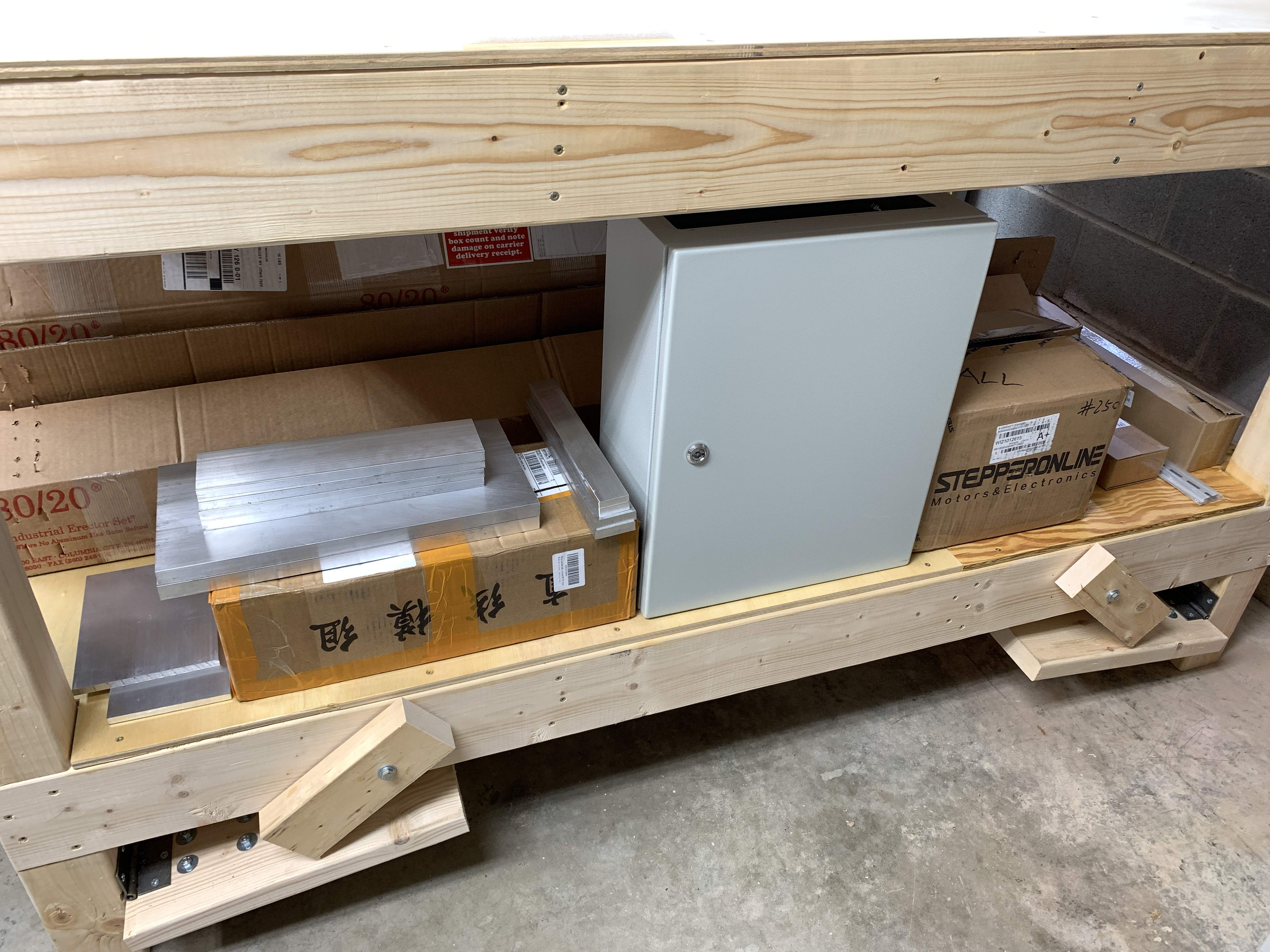
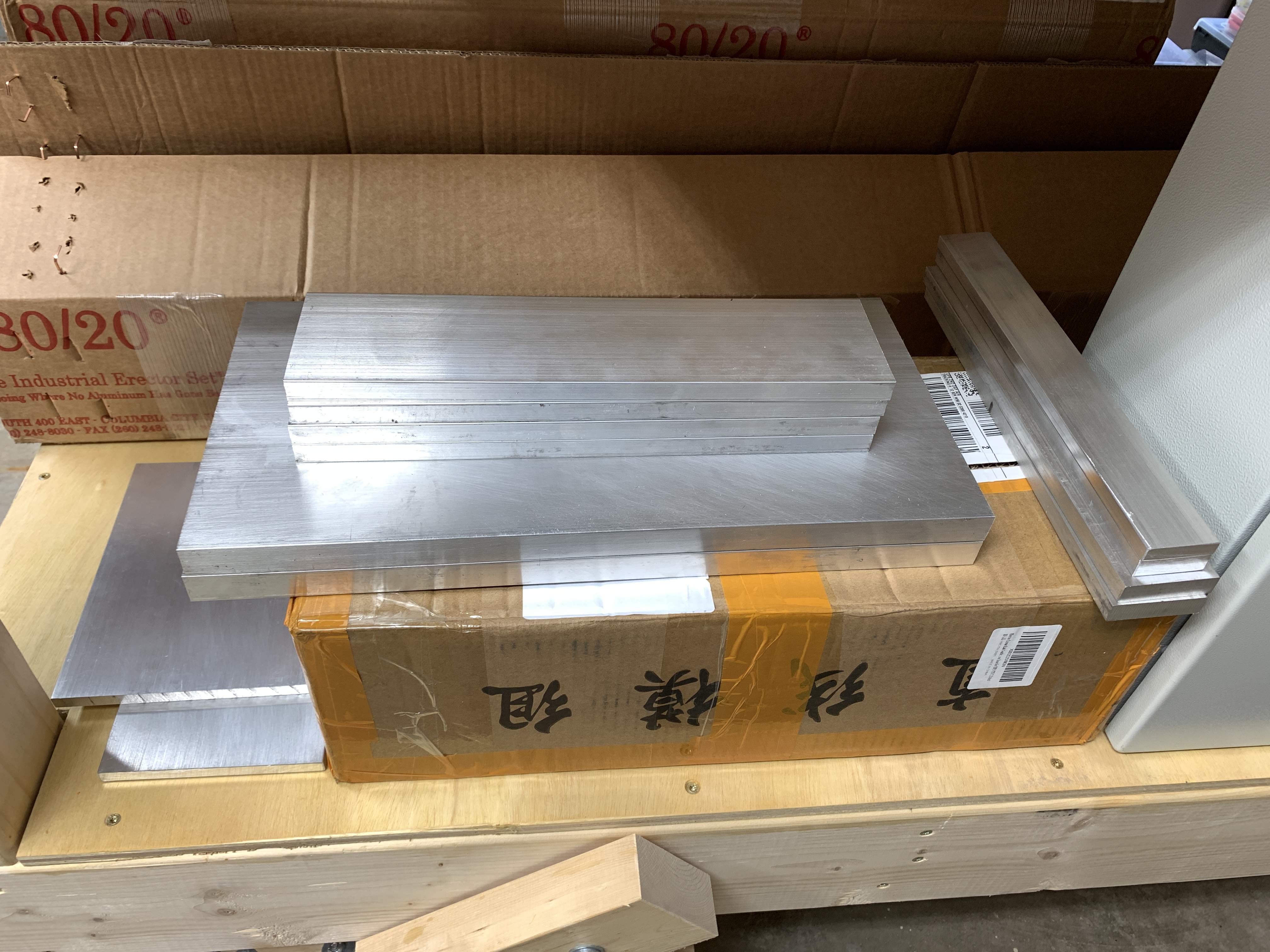
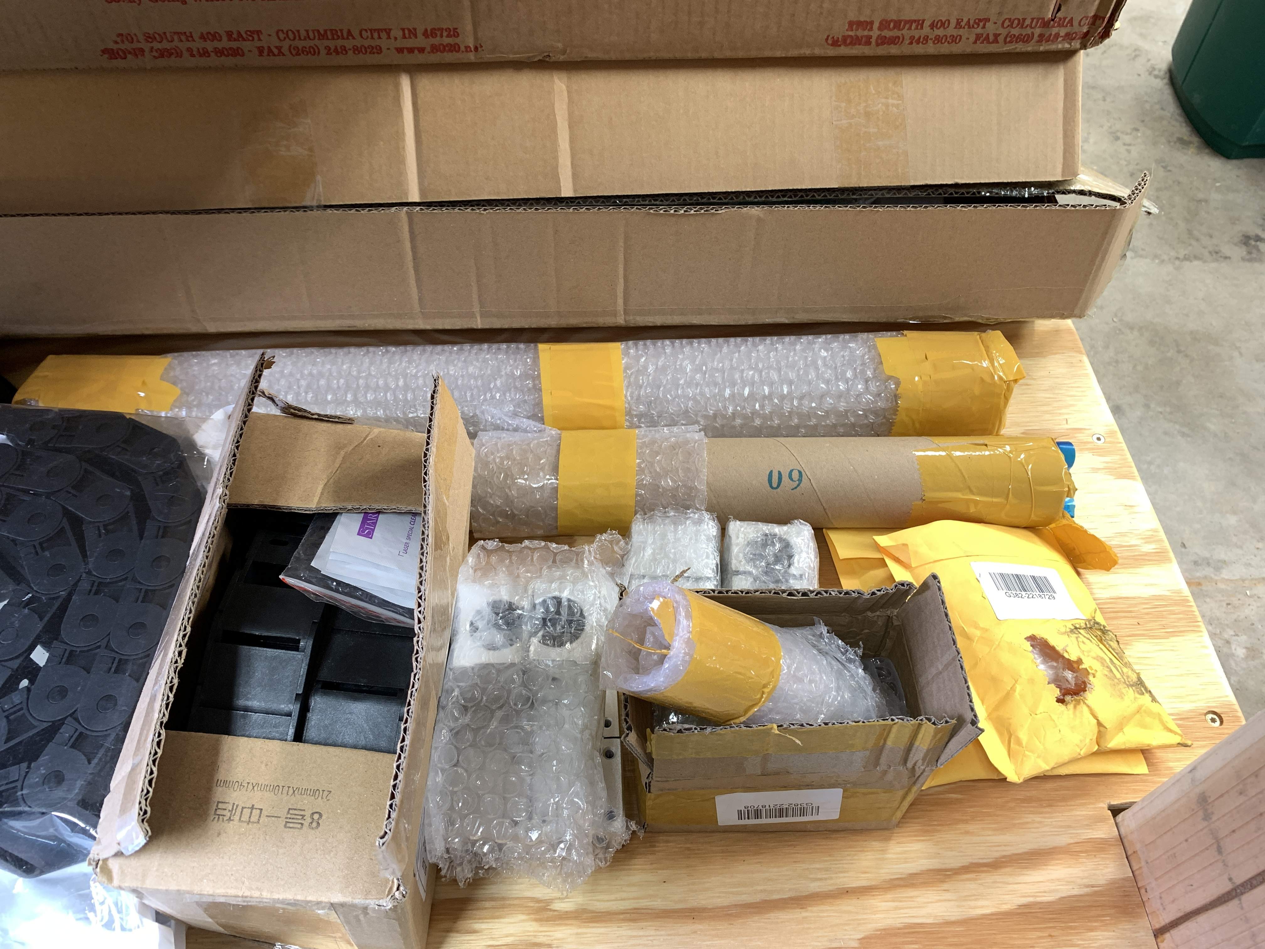
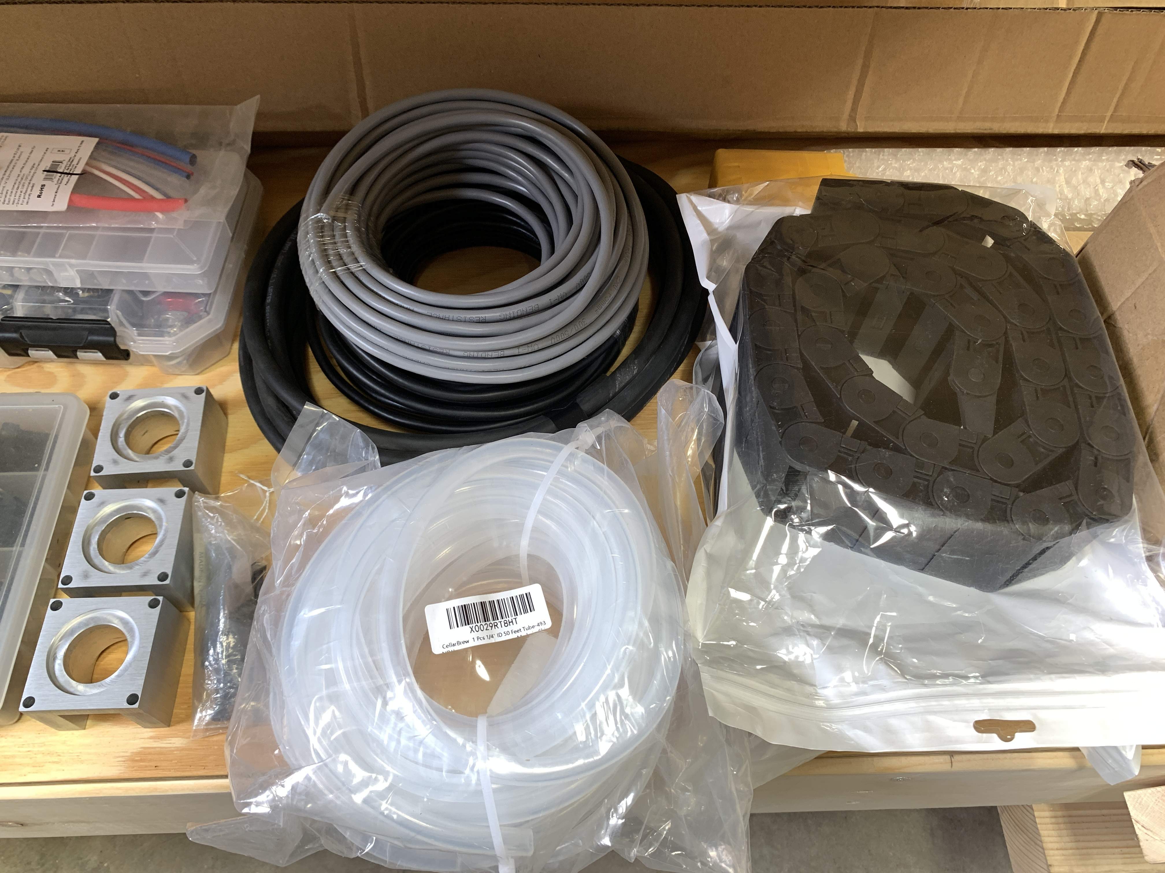
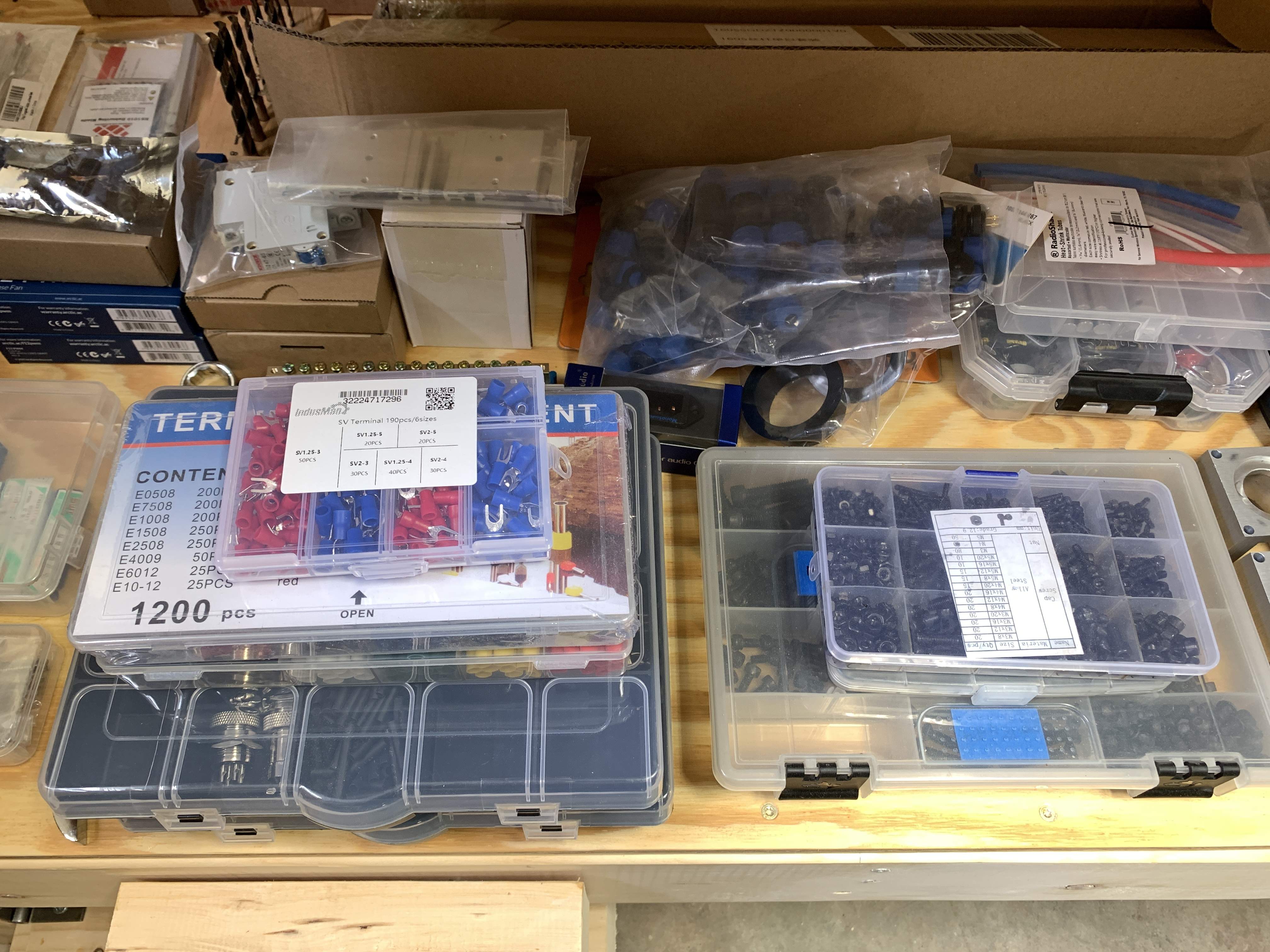
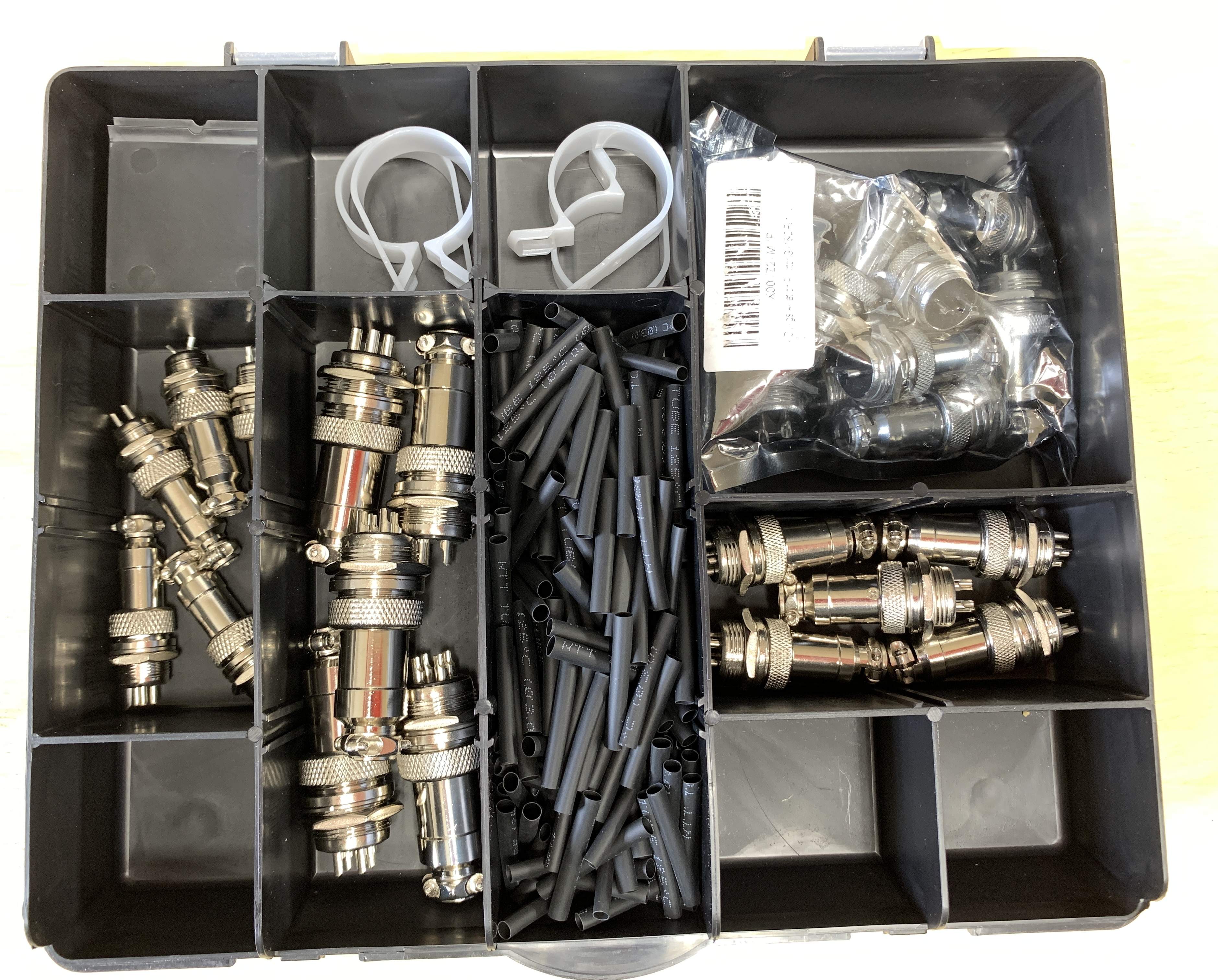
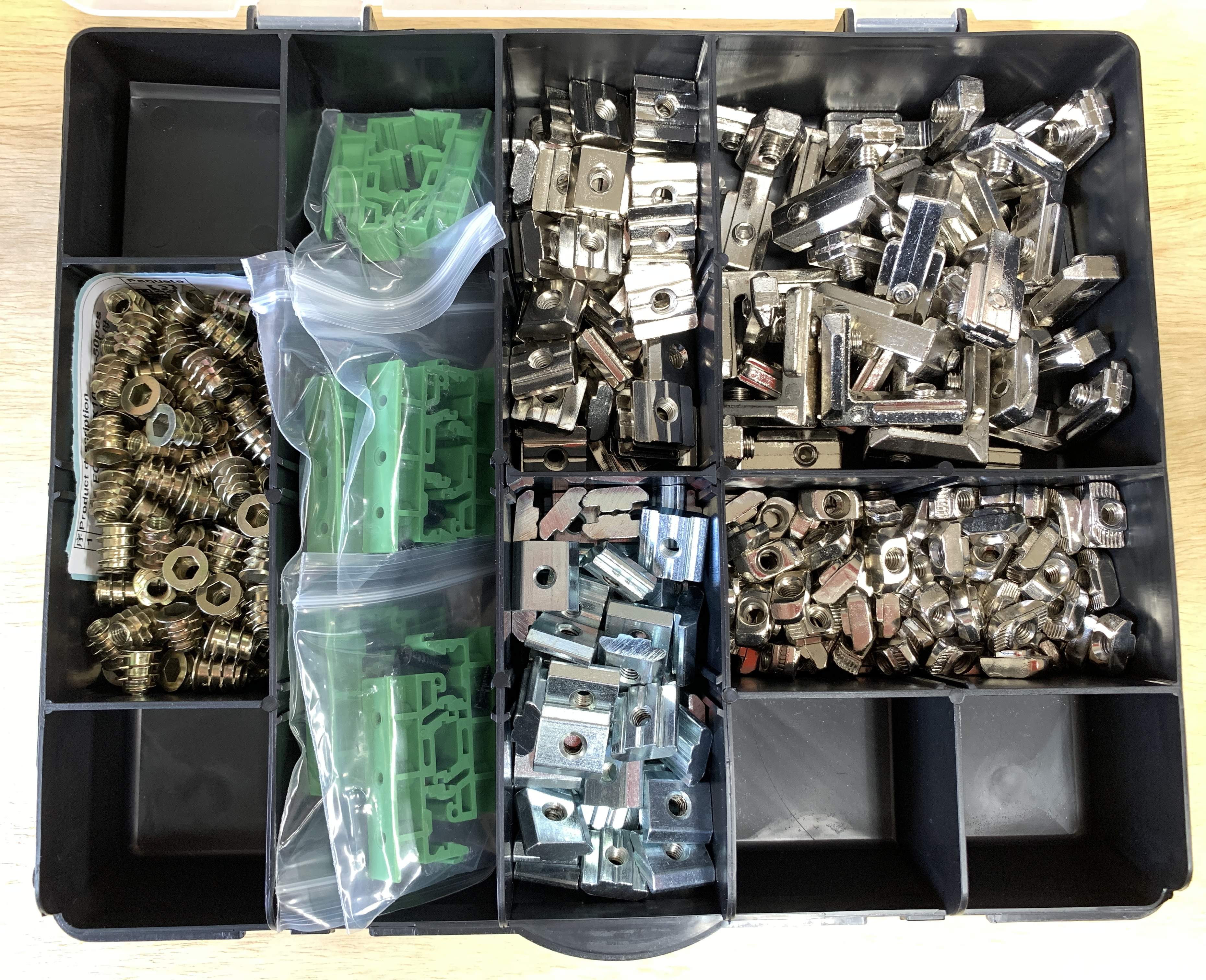
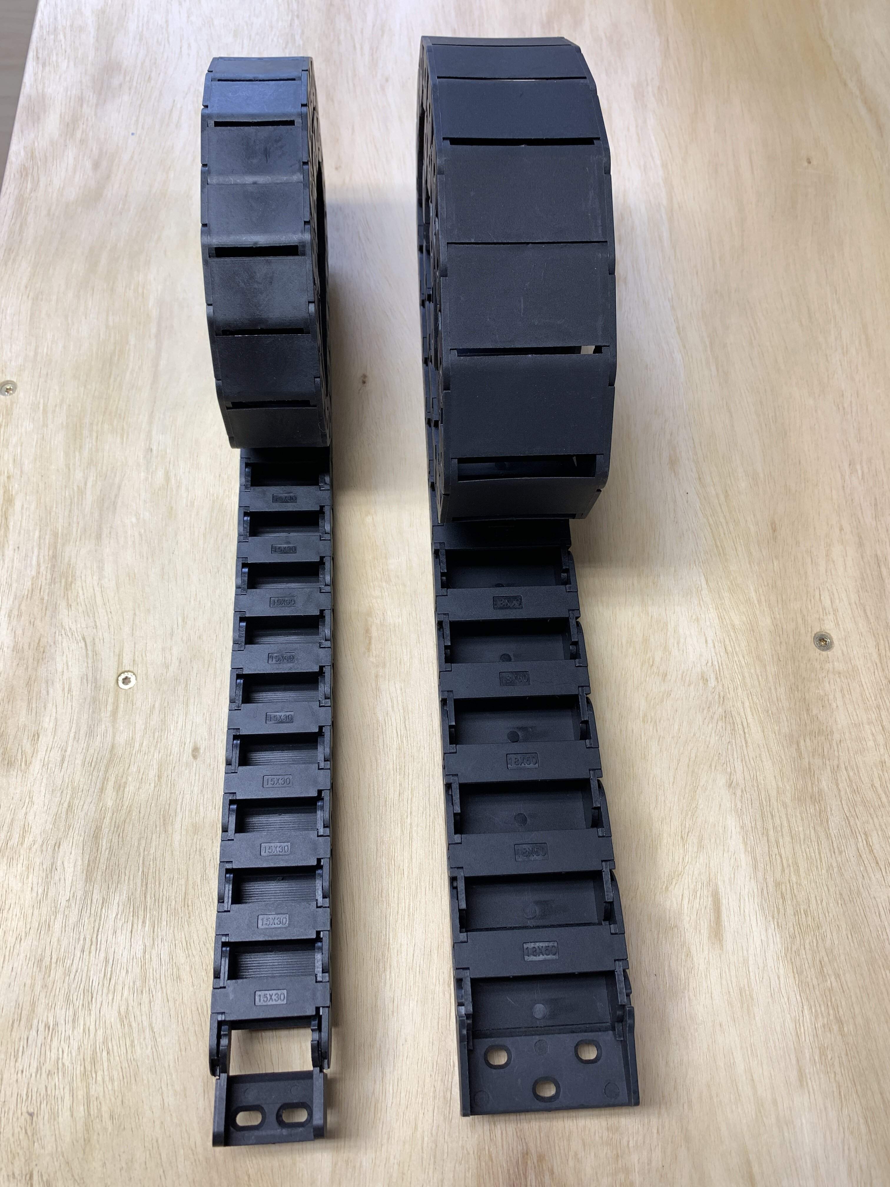
Here are some photos of all the parts ordered so far... there are still more in transit, but most should be delivered in the next few weeks.

IMG_1038.JPG


IMG_1037.JPG


IMG_1040.jpg


IMG_1041.jpg


IMG_1042.jpg


IMG_1043.jpg


IMG_1013.jpg


IMG_1014.jpg


IMG_1015.JPG


IMG_1016.jpg
 
While I have zero experience in either building electronics, working with design software or a CNC, the one attribute I do have is a determination to learn new things. As each step is reached, I do some research on it, to ensure I'm headed in the right direction or if there is a better, more elegant solution to each stage.

Yesterday I began the CNC build. First on the agenda is to build the frame, then to cut, drill, tap and prepare all the aluminum parts required for the structure.

Let's get it started....

First make sure all the structural aluminum extrusions, linear rails and ball screws needed are present and accounted for.

IMG_1046.jpg


You will notice in the photo above that the Z Axis is missing. It is a complete kit setup and will make an appearance in the near future. Before I can mount the Z Axis, more parts are needed, mostly the Spindle/VFD kit because the spindle mount is needed to drill and tap the holes needed to mount that to the Z Axis slider and to mount the Z Axis slider kit to the X Axis Linear Rail bearings.

The first step is to mount the 1500mm linear rails to the 1525mm 3060 Aluminum extrusions. So the nuts were slid into place, the screws lightly screwed in so the linear rail could be measured and aligned properly. Once everything was measured. it was tightened down.

IMG_1047.JPG


IMG_1050.JPG


For those that did not read my previous thread, a set of plans was purchased from Chris Monck from Highline Guitars (he has a YouTube Channel) and this is what I am following for the structural parts of this build. With this in mind, the plans show where to add the nuts required for future steps. Nothing worse than having to take something apart because you left something out!

Of course whenever my grimy hands get on something, it gets modified. In this case, the length needed to be long enough to build a neck through bass.

The one aspect that should have been considered before starting on my buying spree (which started when this was going to be a router sled) is to make the X Axis at least 48 inches wide. Since I've already sent back a bunch of parts and structural aluminum has been sent back to 80/20 once already. I'm just going to stick to the design Chris used, so the current width will be used.

Fortunately, this CNC is being built in a modular manner. In the future it will be simple enough to make it wider. In that case the X Axis will need to be stiffer. When building the machine, the cables/wires and cooling tubing will be made long enough to make these modifications in the future. Nothing worse that having to redo something you may change in the future.

IMG_1051.JPG


Next the right angle connectors were put in place, so the frame could be bolted together.

IMG_1052.JPG


IMG_1053.JPG


Of course there was a small issue, because the length of the Y Axis was extended an additional cross brace was added and of course.... there were not enough right angle connectors. An order was placed with Amazon and they will be delivered on Monday.

So we have a very partially assembled frame....

IMG_1054.JPG


More to come.....
 
Well it looks like I made another big boo boo.... The 16mm X Axis supported round linear rails are too short!! They are 600mm and I need 700mm!!

So the 16mm X Axis rounded rails are going to be returned. And I purchased 20mm square linear rails... which won't arrive until Friday.

http://rover.ebay.com/rover/1/711-5...0001&campid=5338148343&icep_item=184218237802

It's crazy how easy it is to make mistakes... especially when you don't have a plan in the beginning. It's because I started out with the idea of building a router sled. And switched lanes part way through... hopefully now everything is straightened out??
 
As an eBay Associate, TalkBass may earn a commission from qualifying purchases.
  • Like
Reactions: Beej
On the other hand, here is the Z Axis slider setup purchased for this CNC.

It has a built in motor mount and optical limit switches. The best part is it has a narrow footprint. Since the mistake I made with the too short linear rails, replacing the round ones with the bearings with flat rails and bearings will make the footprint even narrower!!

I guess in a way, the mistake turned out to be a very good thing.

img_1073-jpg.jpg


img_1074-jpg.jpg


For those who are building your own CNC machines, please keep in mind that in order for spindle to be "square" and level with the entire spoil board, you will need to leave some room for adjustment.

Sure, using the CNC bit to level the spoil board can help in this task, the truth is that you need the ability to adjust in both axis' in order to make sure everything is perfectly set up.

You can make your own tool to adjust the spindle perfectly, which is called a tramming tool... or spend a bunch and buy something like this!

If you see "steps" when you level your spoil board in either direction, it's because you need to tram your machine. Please understand that I am new to this stuff and only found out how important this is because of all the searching and research I've been doing.

screen-shot-2021-05-09-at-10-12-57-pm-png.png
 
Watching with interest! What do you estimate will be the total cost for this build?

Thanks!!

The guesstimate is somewhere between $2,500. and $3,000.

It adds up quickly when you use high quality parts and do crazy things... for instance, instead of using a computer to run the CNC, I'm purchasing an all-in-one unit called Masso, in addition I ordered it with a pendant. total cost for that part alone (with a 5 axis license) was just over $900.

The Z Axis set up above was $319. The stepper motor kit (including the 2 power supplies, 4 stepper drivers and 4 stepper motors) was $324.00 The spindle/vfd kit was $425.00 etc, etc...

In addition silly ideas like how to control the fans cost a bit of money...
How a simple Router sled turned into a manual CNC / Mill hybrid & maybe more?

It's really fun figuring this stuff out and learning as I go along. I hope those following along enjoy my strange process
 
Next up was to create templates so that all the drilled holes in the aluminum would be in the same place on the multiples of similar parts. So first I laid out the paper templates the same way we have done for guitar building...

img_1059-jpg.jpg


Then I realized, I was making a fatal flaw in my process. By making separate templates for each individual part, the holes would not be perfectly the same!

In holding the paper templates up to the light, it was easy to see that almost every single hole lined up with all the others. Yes there are some differences, some not needing certain holes, so a single master template was made for each of the parts.

They were cut out of 1/4" MDF and the holes were all drilled using a 1/8" drill bit. This was done for two reasons. First it is smaller than all of the metric holes that need to be drilled. Second I have a punch set from Harbor Freight that has a 1/8" punch.

img_1061-jpg.jpg


img_1063-jpg.jpg


When you purchase "raw" aluminum bar from any distributor, the edges are pretty darn rough. So I purchased a table saw blade designed to cut aluminum. I figured the edges could be "trimmed" and be cleaner.

Here is the before using the saw blade.
img_1065-jpg.jpg


Here is after using the saw blade.
img_1067-jpg.jpg


Unfortunately, it was only slightly better and just would not do. So the next attempt was to use the ROSS and sand the edges.

img_1068-jpg.jpg


This is much better! Maybe I'll use a sanding block with some 220 grit to polish it up a bit...

The aluminum bar for the Y Axis brackets were too long, so they had to be cut down in length.

img_1071-jpg.jpg


The cut ends still need to be cleaned up on the ROSS.

img_1072-jpg.jpg


For the gantry sides I'm using 3/4" aluminum, but the straight rectangle did not look all that great, so a slight angle was cut. The cuts were done using my table saw sled and some double taped mdf to hold the pieces in place while cutting them. Very shallow depth passes were made to cut the aluminum all the way through.

img_1069-jpg.jpg


img_1070-jpg.jpg


This was done late yesterday and there is more work to be done on the gantry sides before the drilling begins.
 
I mostly love that you are using my tried and true method of "I literally know nothing about this, I should definitely do it!" and then carrying that through every single decision while simultaneously tying it into my other favorite method of "This seems crazy complex for no reason, let's do it that way!" :roflmao: :laugh: :roflmao:

This is so very close to how I feel and how this project has been approached. And I am crazy, so it fits for me.:roflmao::roflmao:
 
It seems like you are going about this the right way. Just be prepared for some frustration, always a good idea to know when to walk away for a little bit to collect your thoughts. Ball screws work really well but do be aware of the maintenance requirements of your setup.
 
  • Like
Reactions: John_Nicholas
It seems like you are going about this the right way. Just be prepared for some frustration, always a good idea to know when to walk away for a little bit to collect your thoughts. Ball screws work really well but do be aware of the maintenance requirements of your setup.

I'm very prepared for frustration. Not sure you could ever build a guitar and not come up across frustration. LOL

Thank you for bringing up the aspect of maintenance, that is something I've been thinking about a great deal but have not done any research on yet.

Actually maybe you could point me in the right direction. I'm very concerned about the setup when brand new. How should the rails, bearing and ball screws be prepared when building??

When I used to race Motocross motorcycles, I would take apart nearly every single bearing, clean it and lubricate it properly, plus drain the engine and transmission oil and replace it will quality oil. I imagine these bearings, ball screws and linear rails (which are mass produced) should be addressed before assembly. Any suggestions?
 
I know a bunch of people hate on Amazon, but damn, when you need something you get it in two days. Since I ran out of the right angle brackets, more were needed. The last set were ordered from China (yes they were cheaper) but took 4 weeks to get here.

So now I can at least finish up assembling the base.

IMG_1075.JPG
 
And of course another box arrived today as well... the spindle/VFD kit.

This thing is so very cool!! I'll probably sell off the water pump because I'm not going to use it!

IMG_1080.jpg


IMG_1078.jpg


IMG_1079.jpg


IMG_1088.jpg


IMG_1089.jpg


IMG_1094.jpg


For those that have these kind of spindles, I have a question about the holder bracket. The two outer bolts are threaded into the lower part of the clamp, which is to be expected to hold the spindle. But the center bolt is not, it has threads in the upper part of the clamp and no hole or treads in the lower part. It's kind of difficult to see, but I attempted to take some photos.

What do you think?

IMG_1085.JPG


IMG_1084.JPG


IMG_1086.JPG


If this is a manufacturing defect, I will return it.

More to come.... I promise!