- Dec 20, 2004
- 4,267
- 2,481
- Disclosures
- Player-Builder-Founder: Honey Badger Pickups & Regenerate Guitar Works
This was a sub-topic within another thread here, so it's probably best to shift the discussion into a topic of its own vs. continuing to derail the other thread ...
Here's how I would approach capturing the contour of a bass body from an internet image. I'm intentionally using an image here that isn't aligned perfectly on centerline
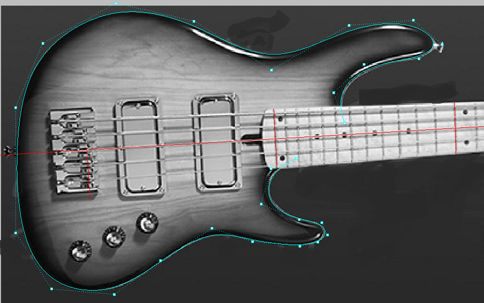
I first established the centerline down the neck, and then set curves at the nut, 12th fret, 24th fret, and G-string saddle. These are the red lines in the image above. These allowed me to scale the image and average in the scale length so I had a full scale image to work against.
Next I created a curve from control points and roughly placed points around the outline. This is the cyan curve and control points. Once you've done a few of these you'll get a hang for where you need to place the initial control points.
From there it was time spent massaging the point locations until the curve as at an acceptable accuracy level to capture the body outline. It's ok if the image is a little bit fuzzy so long as your final curve is smooth and as close as you need it. This would have been a nightmare to work with downstream if I was obsessed with ensuring I placed points ON those fuzzy edges.
Once I have the curve close enough, I'll analyze the curve for smoothness. There are a couple places where I'd want to work this curve further, but I'm sure you get the concept.
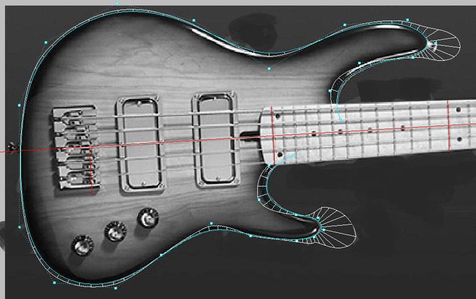
Note that I'm using a familiar body outline here for reference. I do NOT have this outline as any part of my design libraries. I'm using the familiar body shape purely as reference, and using this instead of one of my own body shapes since my shapes would not include a scanned image as part of their design workflow.
An additional image on curve analysis, comparing the smooth curve created with the above workflow, and a fillet that was placed manually. Notice the drastic vectorin change that occurs right where the fillet is tangent to the smooth curve. If you're utilizing this curve with any kind of CNC, you're going to hear that during the machining process when the tool path comes to this location on the curve.

And similar to the workflow used to trace an image and develop smooth curves, here's a peek at the upper horn curve control points
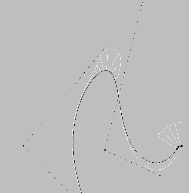
I'm using Rhino as the CAD tool here, but the process is similar with most any CAD tool that utilizes relational geometry, so you would take a similar approach with CATIA, SolidWorks, AutoCAD, ProE, DraftSight, etc ... The exact command and mouse click will be in-step with your CAD flavor of choice.
Here's how I would approach capturing the contour of a bass body from an internet image. I'm intentionally using an image here that isn't aligned perfectly on centerline
I first established the centerline down the neck, and then set curves at the nut, 12th fret, 24th fret, and G-string saddle. These are the red lines in the image above. These allowed me to scale the image and average in the scale length so I had a full scale image to work against.
Next I created a curve from control points and roughly placed points around the outline. This is the cyan curve and control points. Once you've done a few of these you'll get a hang for where you need to place the initial control points.
From there it was time spent massaging the point locations until the curve as at an acceptable accuracy level to capture the body outline. It's ok if the image is a little bit fuzzy so long as your final curve is smooth and as close as you need it. This would have been a nightmare to work with downstream if I was obsessed with ensuring I placed points ON those fuzzy edges.
Once I have the curve close enough, I'll analyze the curve for smoothness. There are a couple places where I'd want to work this curve further, but I'm sure you get the concept.
Note that I'm using a familiar body outline here for reference. I do NOT have this outline as any part of my design libraries. I'm using the familiar body shape purely as reference, and using this instead of one of my own body shapes since my shapes would not include a scanned image as part of their design workflow.
An additional image on curve analysis, comparing the smooth curve created with the above workflow, and a fillet that was placed manually. Notice the drastic vectorin change that occurs right where the fillet is tangent to the smooth curve. If you're utilizing this curve with any kind of CNC, you're going to hear that during the machining process when the tool path comes to this location on the curve.
And similar to the workflow used to trace an image and develop smooth curves, here's a peek at the upper horn curve control points
I'm using Rhino as the CAD tool here, but the process is similar with most any CAD tool that utilizes relational geometry, so you would take a similar approach with CATIA, SolidWorks, AutoCAD, ProE, DraftSight, etc ... The exact command and mouse click will be in-step with your CAD flavor of choice.