• TalkBass has been independent since 1998. Add your voice.
    Create a free account to reply to discussions, view embedded media, and browse with fewer display ads.
    Join freeLog in
    Want zero display ads or expanded classifieds tools? Compare plans.

Custom tuners

Mar 14, 2016
1,336
3,042
Denver
I've been off the forum for 4 years, but I just started a new project with some solid players and this part of my current build is fun and weird so I thought I'd share it. I'm doing a headless from scratch, and I was not happy with commercial tuner/bridge options.
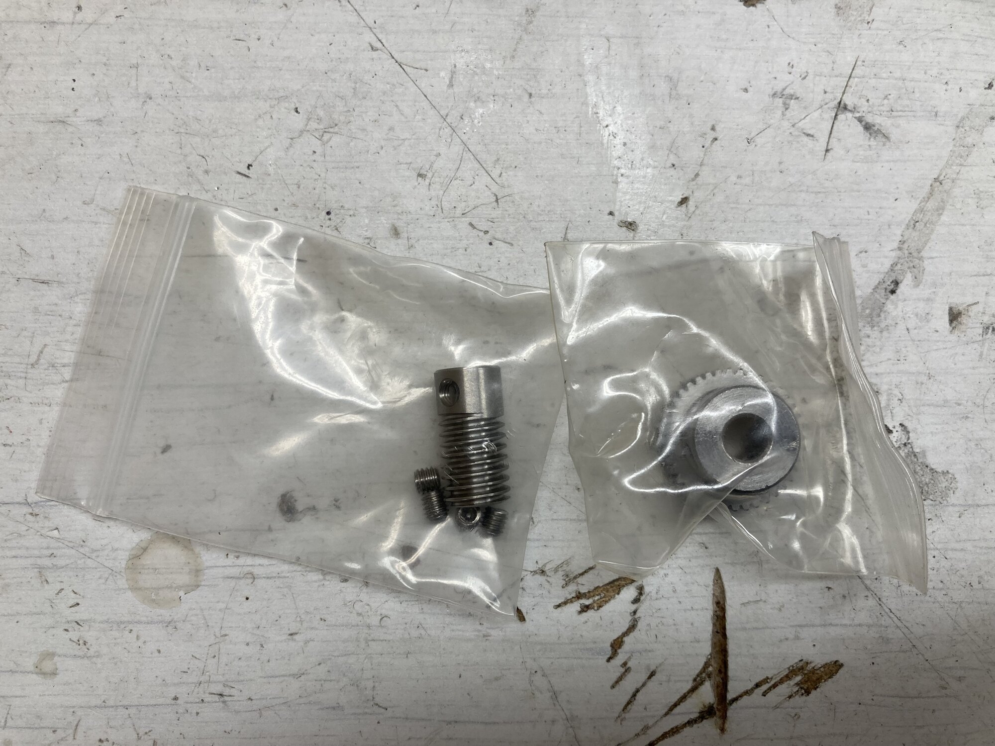
I got these 40:1 worm gears before the tariffs kicked in:
IMG_2241.jpeg

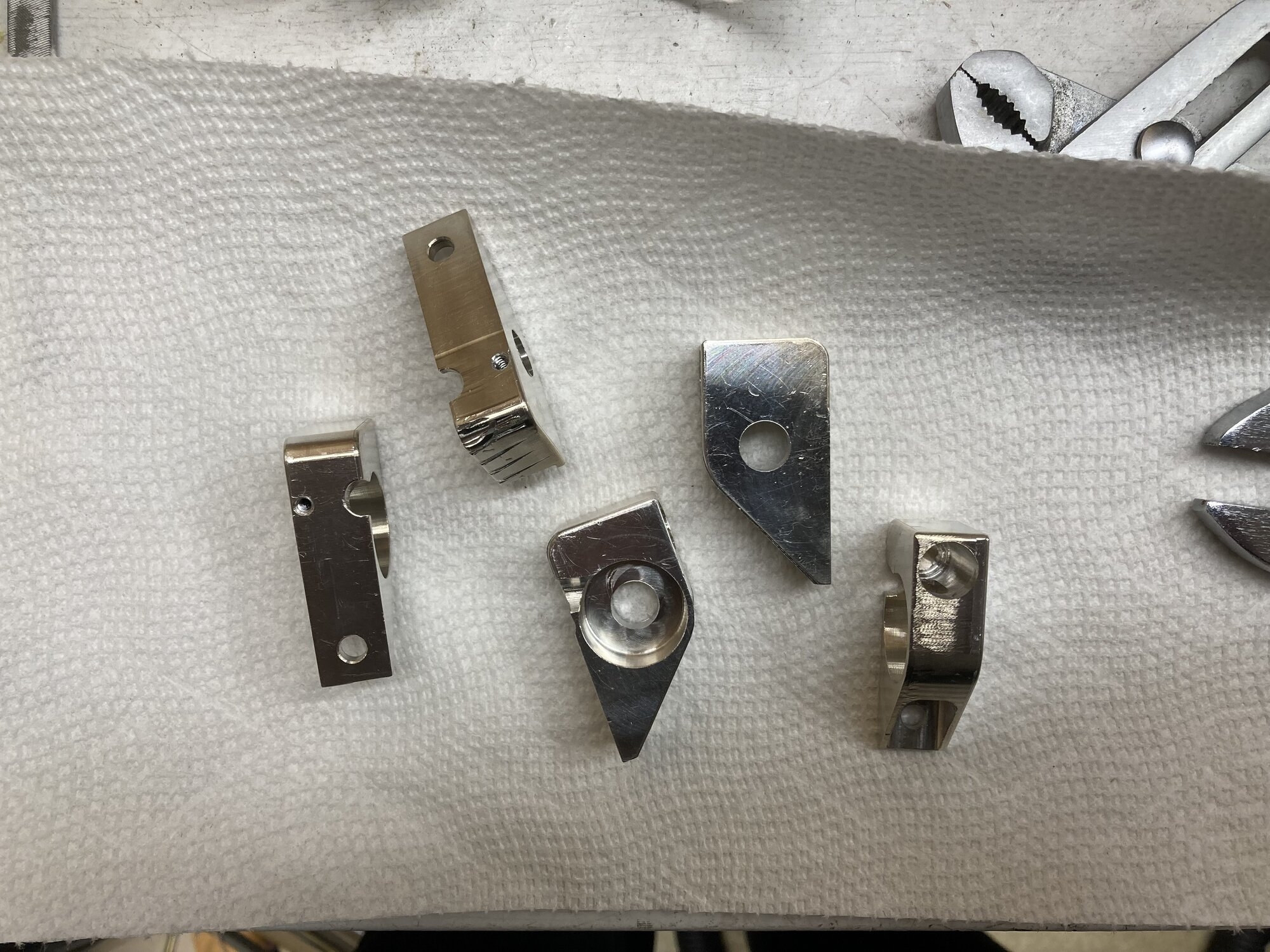
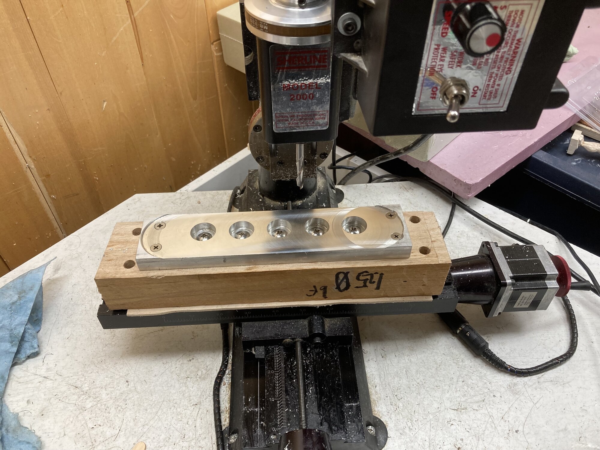
For housings, I designed something relatively simple, and machined 5 at once:
IMG_1910.jpeg

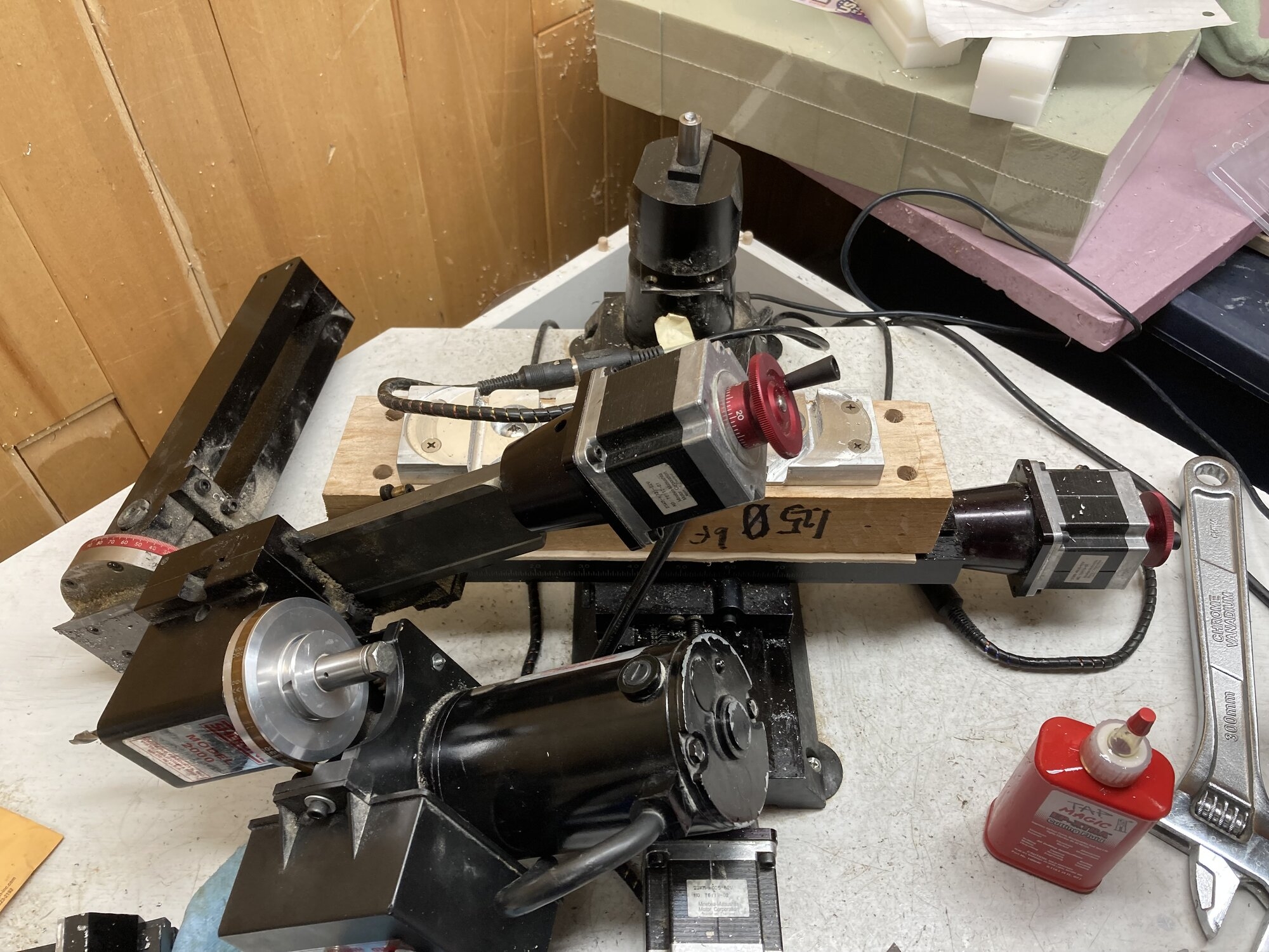
Unfortunately I got kind of aggressive with my speeds and feeds, and exceeded the rigidity limits of the mill. As I went to tighten things down, I broke it in half.
IMG_1911.jpeg

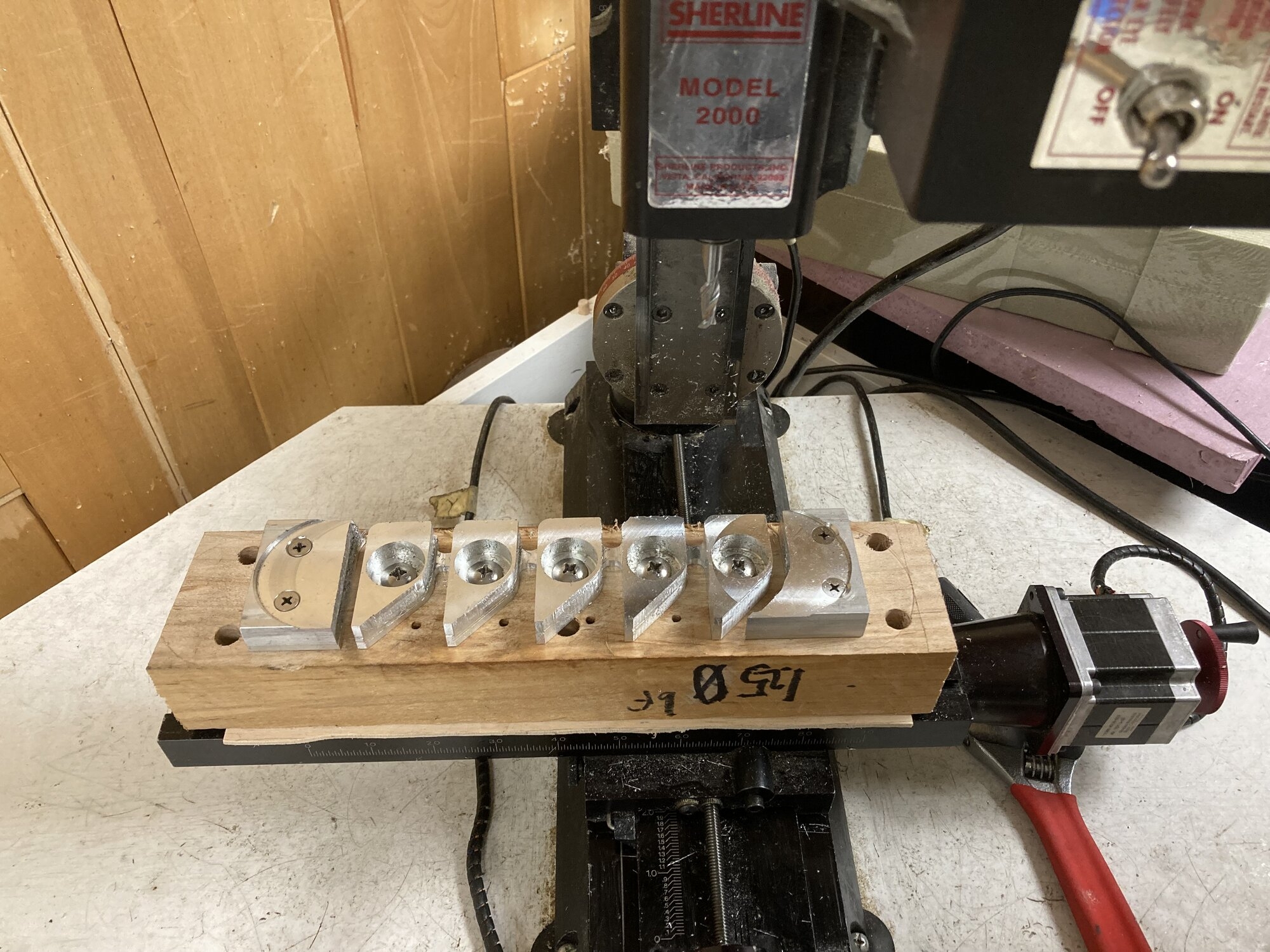
Once I got a new bolt and slowed things down, results improved.
IMG_1942.jpeg

IMG_1982.jpeg

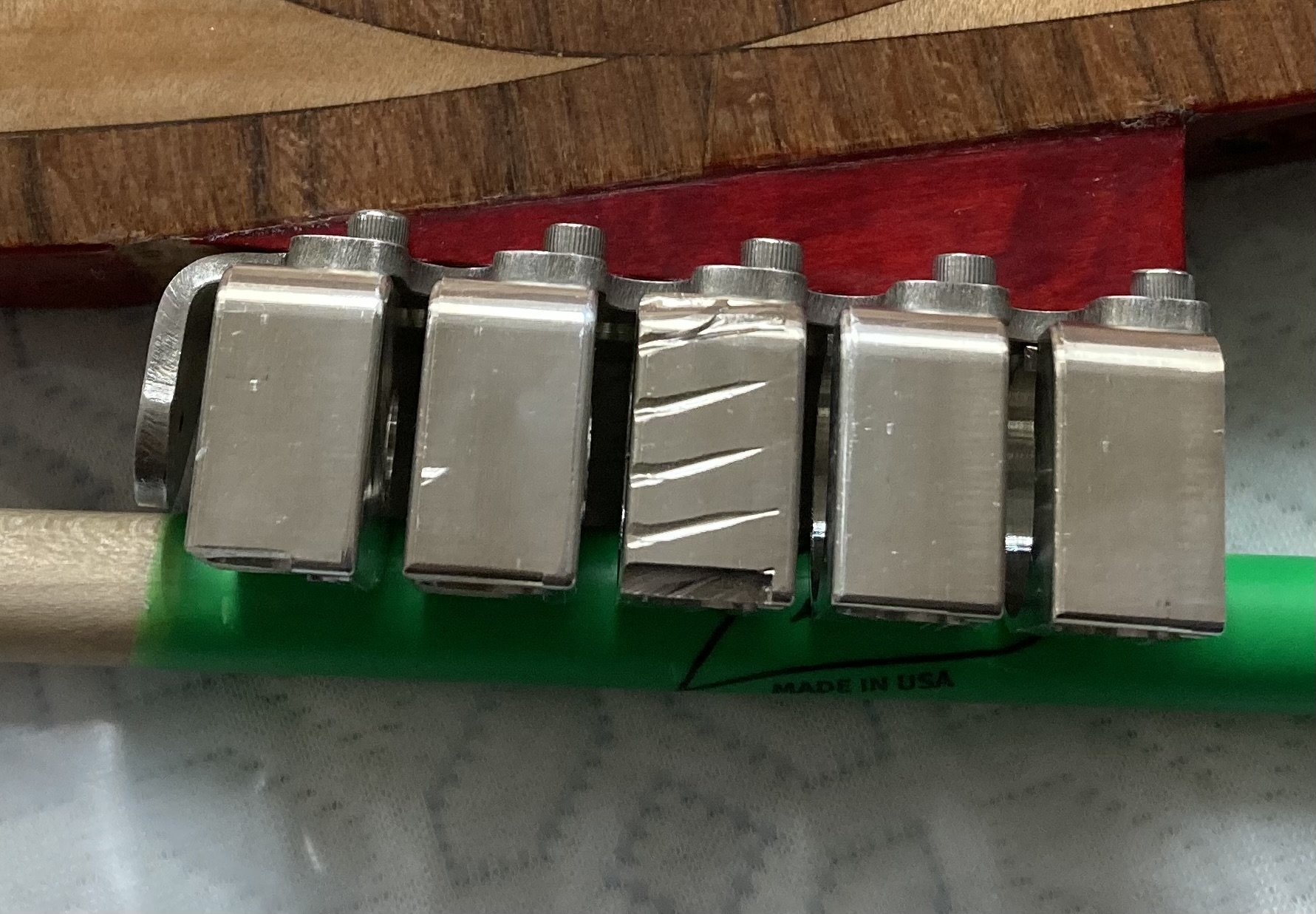
You can still see the bite marks from the earlier rigidity fail.

The design calls for drill rod shafts and axles turning in bronze bearings, with a brass tube surrounding the worm itself for lubricity and to provide a wear surface.
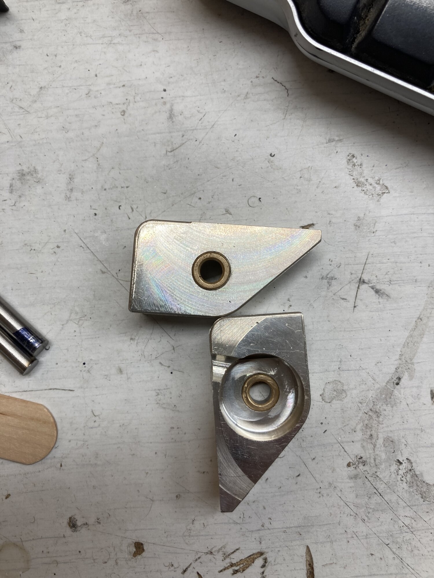
IMG_2236.jpeg

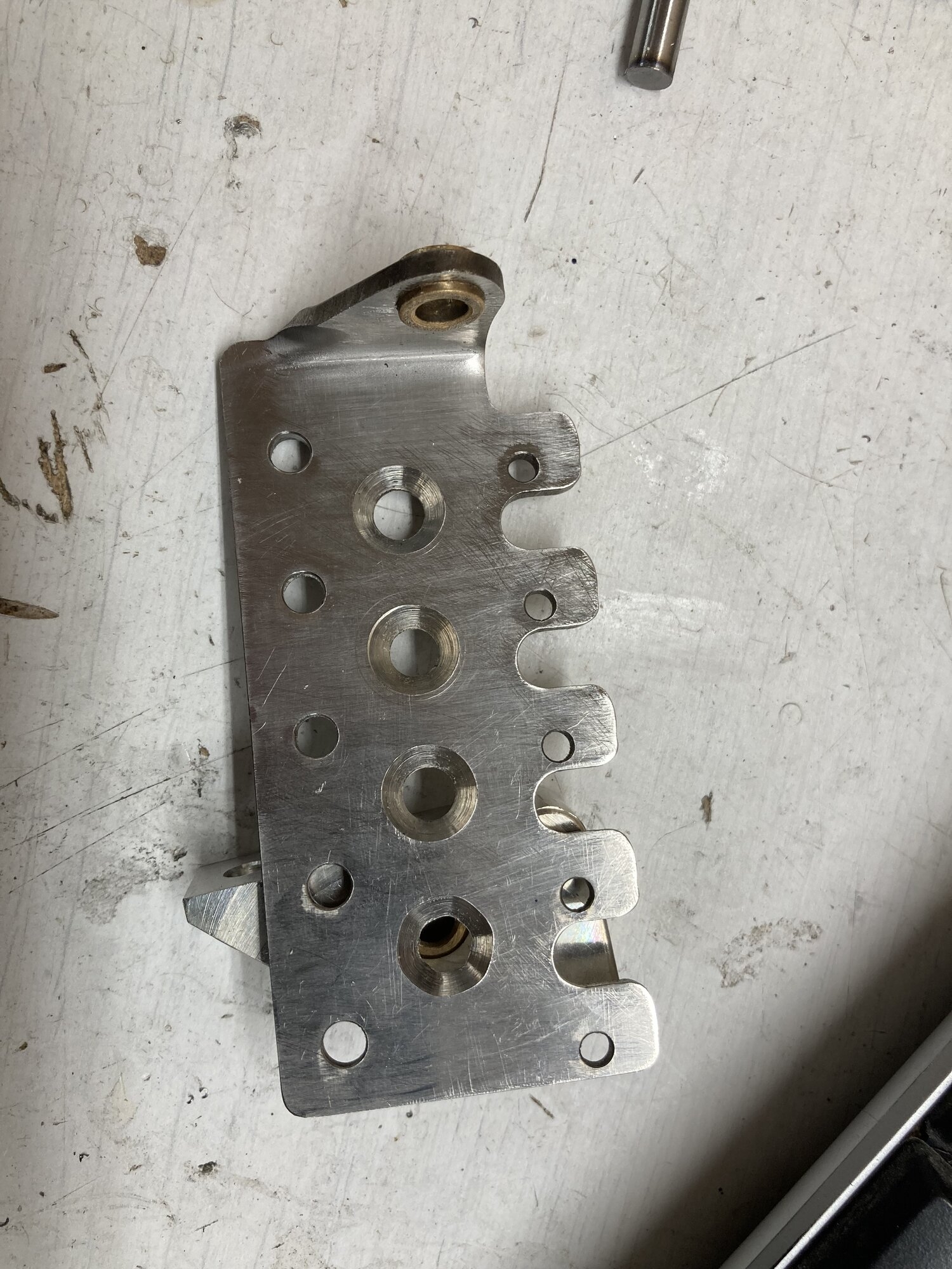
All these aluminum housings are to be mounted onto a stainless plate that provides repeatable alignment and also the last bearing. I had these laser cut and bent by the brother of a friend, then did the finish work.
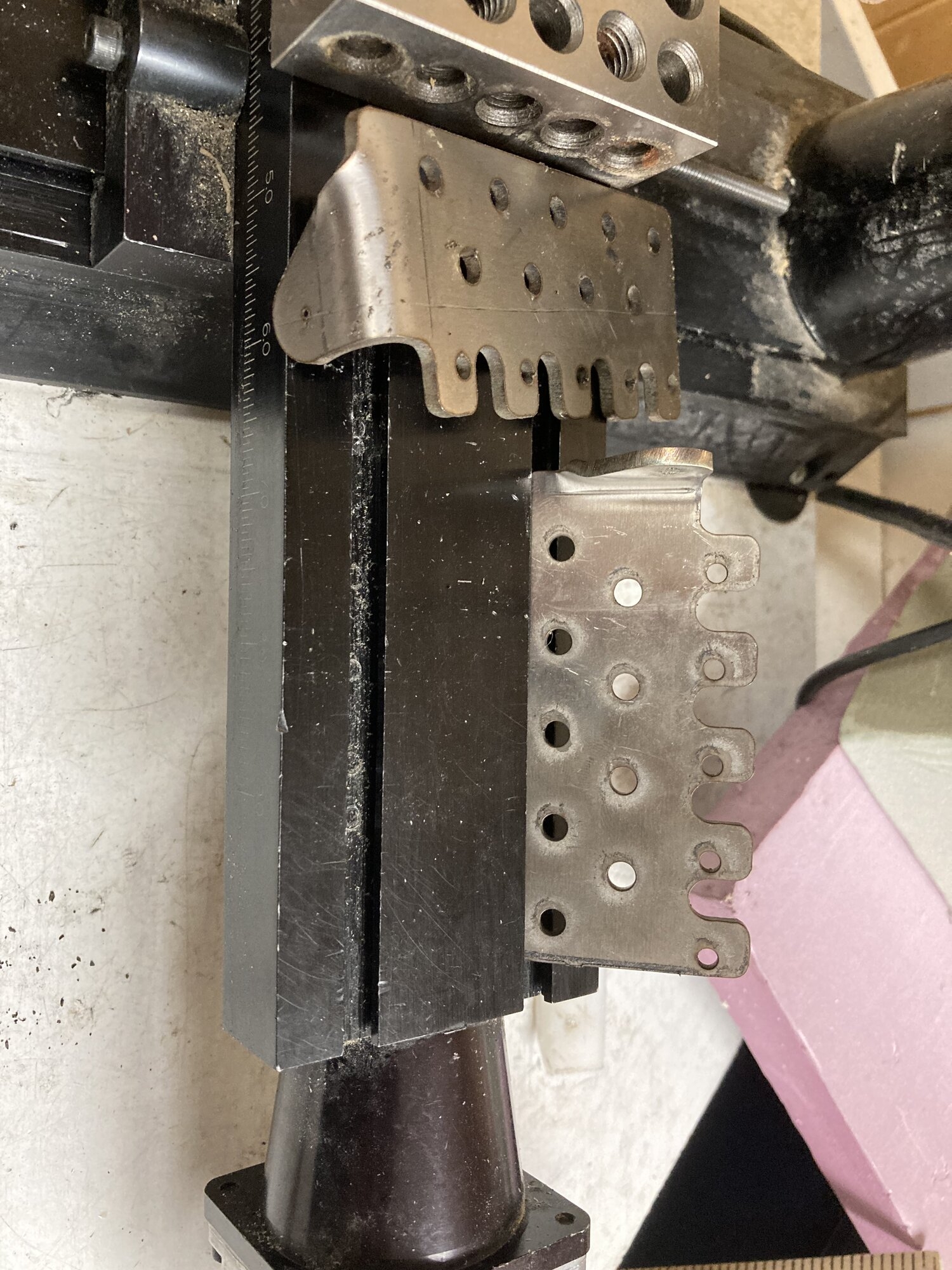
IMG_1907.jpeg

IMG_2239.jpeg

Here's a mock-up mounting.
IMG_1983.jpeg

The axles are easy but the worm shafts are proving harder. In particular I need to find the center very precisely to drill and tap a hole and machine them oblong for the knobs. I thought I had done a good job with my dial indicator but I was wrong.
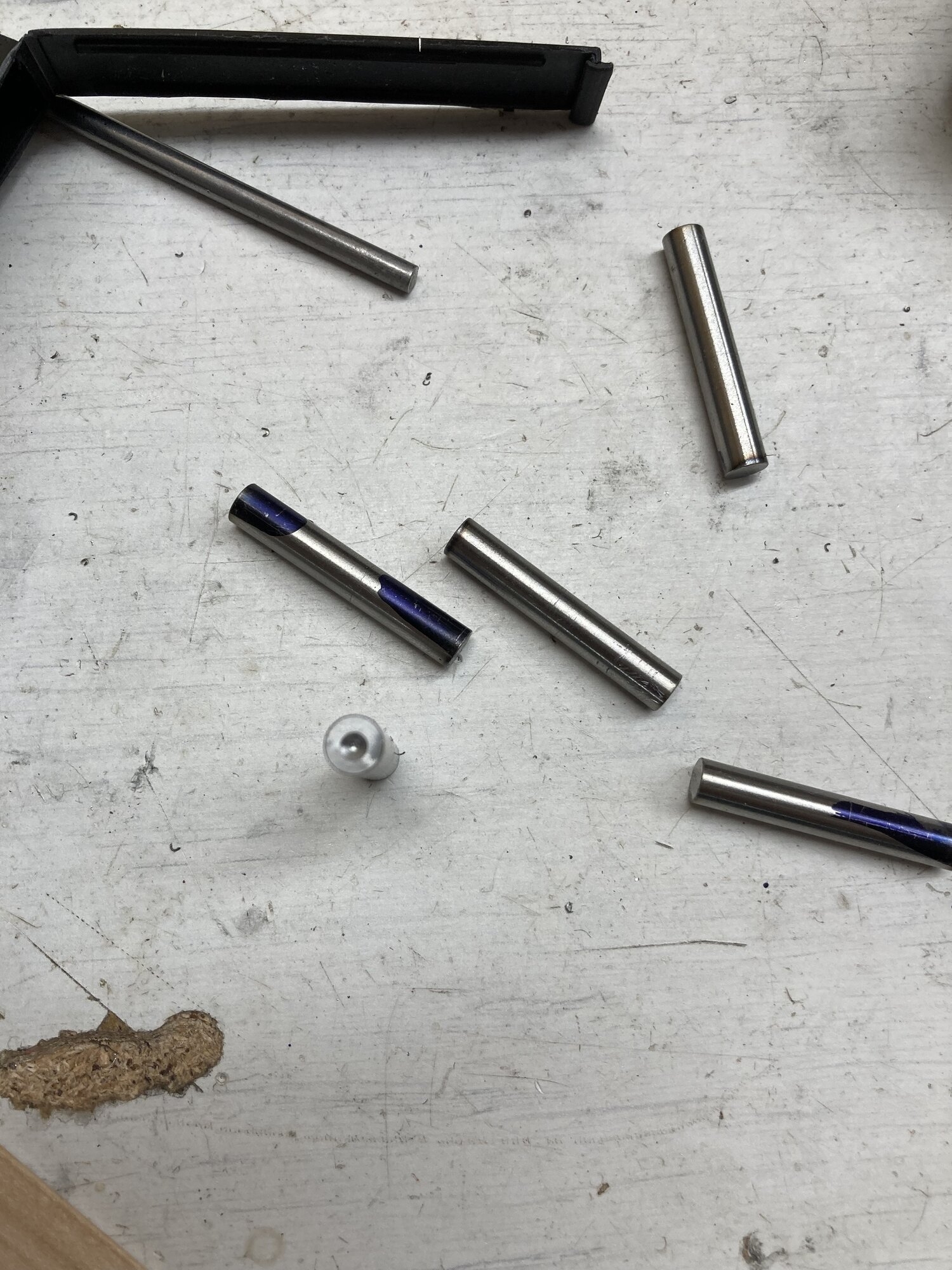
IMG_2237.jpeg

Current plan is to drill a hole in a maple block and clamp the shafts in it for the drilling, followed by machining using the same block.
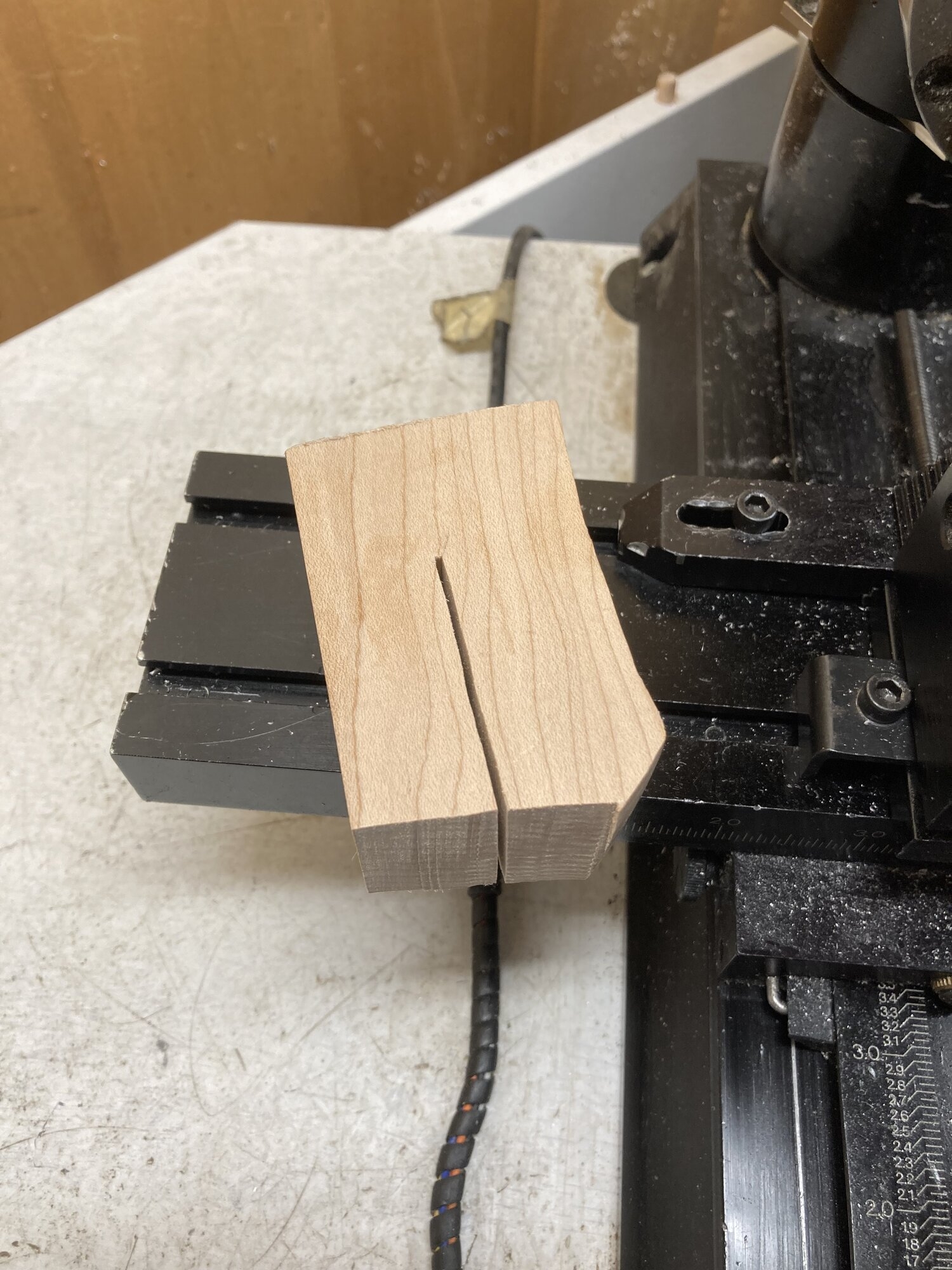
IMG_2238.jpeg

This is probably a Thanksgiving weekend project given that I want to complete it all in one go due to the centering problem.

Knobs will be 17mm aluminum balls with texture machined on them--just realized that while they are designed in CAD, I have never rendered them. I got the balls here before the tariffs too.

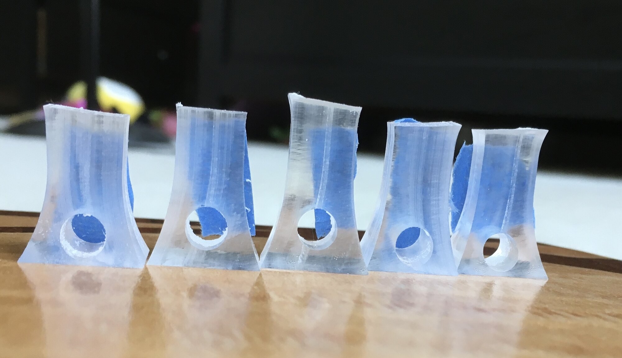
Bridges are acrylic; they are rough machined but obviously need to be hand-cut to height. They will be polished clear when I am satisfied with the action.
IMG_8944.jpeg

I would like to anodize the aluminum parts bright red but the first order of business is to actually have a playable bass. Plus the current parts have the scars of bad machine work so I would probably want to make a clean set.

This will ultimately be a 36" fretted 5-string reverse P with Bartolini pickups and conventional passive wiring. I am currently playing a fretless version with the same dimensions and electronics and liking it a lot.
 
Pretty slick! Curious to see what you come up with for the headstock string anchors. That was always a weak point on the original Steinbergers unless you were using double-ball strings. Is that standard milling machine, or is it somehow CNC run? Looks like a motor running the left/right axis? I'm pretty ignorant when it comes to metalworking tools and fixtures, a subject of regret for me.
 
Here are the anchors in process, with the wood neck-toppers they fit on. I don't seem to have a good picture of these parts after mounting and finishing but the best I can do is a shot of the fretless neck.
IMG_8869.jpeg

IMG_0713.jpeg

The fretless uses ADM tuner bridges that grab the ball. I am hoping on the fretted version to put the ball end at the top and secure the silk end to the worm gear, but it remains to be seen what is possible.

That is a Sherline mini-CNC mill. It is a fantastic tool but needs a couple of mods that I don't have time to do for this kind of work.
 
Unfortunately I got kind of aggressive with my speeds and feeds, and exceeded the rigidity limits of the mill. As I went to tighten things down, I broke it in half.
I canna' change the Laws of Physics, Laws of Physics, Laws of Physics. I canna' change the Laws of Physics, Laws of Physics, Jim!
The axles are easy but the worm shafts are proving harder. In particular I need to find the center very precisely to drill and tap a hole
That's a lathe operation, Ideally. Or a "use your mill like a lathe" if (as I expect) it's the only machine tool you have.
the scars of bad machine work so I would probably want to make a clean set.
That's the trademark "claw marks" of whatever animal (real or mythical) you'll choose to brand them with, and every one will need those added. Preferably after anodizing so they show up well. "At Balrog Bass Tuners, no delving is too deep!" :cool:
 
Last edited:
That's a lathe operation, Ideally. Or a "use your mill like a lathe" if (as I expect) it's the only machine tool you have.
Yes, well, that just reverses the problem from centering the spindle over the shaft to centering a hypothetical tailstock on the spindle. Plus I still need to find the center to mill the shaft oblong (or go 4-axis, which is not impossible but has its own rigidity problems).

Someday I will have a couple of lathes. But this project has been running 9 years and I really want to actually play it.
 
Hear me out? If you have the shaft rotating and a spotting drill fixed in a milling vise, and you barely touch the shaft to the spotting drill, you get a circle scratched in the face if you are off center with the drill bit, a dot if you are on center. The circle will even guide you where to move to get the dot. That's the fundamental difference between rotating the work and rotating the tool.

Or chuck the rod and touch it to some emery cloth or other abrasive held fixed, which will scratch concentric circles into the end. Follow them to the place you should punch, line up the drill point with the punch-mark, and drill (you can swap to having the drill in the spindle once you've marked the end-face.)

Alternatively use a center head on a rule to scribe two crossed lines on the end-face (mill yourself a center head if you don't have one on hand - should be possible to get adequate accuracy with a CNC mill, and adequate useful life in aluminum if you don't beat on it.)

Bruce may have some other tricks up his sleeves, but then, he's a guy with a lot of lathes, too.
 
Last edited:
Another way to drill a hole centered in the end of a shaft, if you don't have a lathe, is to make up a temporary drill guide. Take a block of metal, and drill a hole in it, to slip fit over the OD of the shaft, but only drill partway in. Maybe 1/4" deep. Then drill the rest of the way through with the size drill that you want to drill the shaft. The smaller drill will self-center in the larger hole.

Now, clamp the shaft in the vise, vertically. Set the block of metal onto the shaft. Drill the hole in the shaft down through the smaller hole in the guide block. This can be done in any drill press.
 
I appreciate the suggestions and I may yet try them, but the leave the problem of milling the shaft oblong unsolved. I need it to be non-round so the knobs can turn it, and my goal would be to avoid a set screw (the purpose of the hole in the end is a screw to attach the knob).

An oblong slot is straightforward to cut in the knob, and easy enough to mill onto the shaft...IF I can zero the mill over the center.

I will at least try drilling a hole and zeroing on that and we will see if that works. I have plenty of drill rod if it fails.
 
You need a “last word” or “interapid” style (offset, not plunge) indicator (and appropriate collet, if possible) to center the shaft underneath the spindle of your mill. This is a basic, foundational skill in conventional milling, like tramming your vise (which requires the same type of indicator). Of course, each shaft needs to be aligned with the spindle top to bottom, (in parallax) otherwise you won’t get the indicator to read perfectly.
You are certainly on the right track with drilling holes in stock to receive the shaft, but this can present rigidity problems, so the usual job-shop procedure is to use a vee-block in your vise. It’s pretty easy to make a v-block equivalent by drilling the appropriate sized hole in a squared-up piece of stock, then band saw the piece in half, through the center of the hole. Take care to have the same face of the block against the rigid jaw of your vise when mounting the shaft, that you did when you drilled the hole (magic markers are your friends, no milling job ever suffered from too much annotation…) and have the block in the exact same location in the vise (especially if you’re not tramming the vise, or your table, which I’m guessing is the case).
In service of machining flats on your shafts, I would do this horizontally, as a separate operation. So… before you bandsaw your jig/vee block in half, drill and tap two holes on both sides of the shaft hole, along it’s length. After sawing the block in half, enlarge the holes on one half to be through holes (of course, this can also be done before tapping, when drilling the tap holes, but would require some care and extra measuring) and get four appropriate machine screws to make your jig into a clamp. This can then be mounted in your vise and you can just mill the flats horizontally, which will give you much better results than trying it vertically. Drill rod is pretty hard, taking that cut vertically puts stress on the endmill which might result in a rough finish or premature wear on the flutes.
If making this jig is too time consuming, just get a small v block and clamp set (ideally two) off eBay or wherever, at the same time as you get an indicator.
I know that some readers here will be rolling their eyes at my suggestions, because at the end of the day, you could be off by .02,, and it would not really matter. The practices I outline here, including tramming your table and vise, should get you easily within .005, the “old times” standard for basic machine work. This will serve you well when it’s time to bolt everything together and it fits perfectly with little to no slop.
There should be plenty of videos on YT illustrating tramming and center finding with an indicator. Again, learning these fundamental practices may seem like overkill, but just like playing an instrument… mastering the basics and fundamentals will allow you to tackle much more complicated pieces with confidence. Good luck!
 
Is this the type of indicator you're referring to?
IMG_2249.jpeg

I have used these in the past to center over holes (and tram the head) but this time two separate attempts to align shafts failed. I'm not sure why but I think the need to offset from center to be outside the shaft may have caused (again) a lack of rigidity.

Also, as you can see, these Sherline mini-vices have vees that are probably better than any I can make.

The reason I am attempting to cut the flats vertically is because flats alone are not sufficient. I need the ends to be 1/16" radius to fit in a slot cut into the knob by a 1/8" end mill. That means either milling with the shaft vertical or mounting a rotary table horizontally as a 4th axis. I do have that ability in principle but it's going to create numerous other problems.
 
Is this the type of indicator you're referring to?
View attachment 7362309
I have used these in the past to center over holes (and tram the head) but this time two separate attempts to align shafts failed. I'm not sure why but I think the need to offset from center to be outside the shaft may have caused (again) a lack of rigidity.

Also, as you can see, these Sherline mini-vices have vees that are probably better than any I can make.

The reason I am attempting to cut the flats vertically is because flats alone are not sufficient. I need the ends to be 1/16" radius to fit in a slot cut into the knob by a 1/8" end mill. That means either milling with the shaft vertical or mounting a rotary table horizontally as a 4th axis. I do have that ability in principle but it's going to create numerous other problems.
If you need a radius just to fit in a slot, hand filing the radius ought to be fine. You've only got 4 (or 5?) of them.
 
If you need a radius just to fit in a slot, hand filing the radius ought to be fine. You've only got 4 (or 5?) of them.

Yeah, I agree. For a couple of small parts, you could just hand file the flat sides and radiused ends to get to an accurate oblong shape. There's not much metal being removed, and it won't take much time.

I make up custom tuner posts to fit Hipshot HB1 tuners, and they need two flats milled on the end to go into the oblong hole in the gear. I cut the flats in my milling machine horizontally, using a Spin Index Fixture and a 5C collet.

G00039.jpg


That's my favorite way to do them in limited production, non-CNC. With the Spin Index fixture, It only takes two seconds to roll the part an accurate 180 degrees. I dial the depth down carefully, milling both sides, while measuring the distance across the flats. Once the depth is set and locked, it's quick to do a batch of parts,

IMG_8655B.jpg


These don't require small radiuses at the edges of the flats. If they did, I would just hand file them.
 
I may end up filing if I have to, but I usually find the filing process frustrating so I seek to avoid it. It would also make it difficult to apply the small fillet radius I was planning on leaving at the base of the flat to minimize cracking hazards.

Here are a couple of renders of the knob and shaft as drawn.
IMG_2251.png

IMG_2250.png
 
Taking advantage of the 4-day weekend to get the worm shafts cut.
IMG_2318.jpeg

The drill-hole-in-wood-block method of centering worked out OK. This machine is not really a great choice for working drill rod; I could see it flexing when drilling so the tapped holes are about +/- 5 mils or so and the center for drilling is not the center for milling.

Tomorrow I hope to fit the thrust bearings for the worms and modify the gears to have a string channel.
 
It occurs to me that I never had a centering problem. The machine flex in the drilling operation convinced me that I did because the center-drill dimples were off-center. But if I had started milling then and there, it would have been fine.

Anyway, sleeve bearings are in, when the loctite dries I can machine the excess away. Thrust bearing is going to be a challenge. It's 6mm/.236" thick, and the design calls for .080". An interesting work-holding problem.
IMG_2321.jpeg
 
So to try to machine these bronze bearings down into borderline washers, I made a little plastic holder that was meant to stabilize them while I clamped them in a 3-jaw chuck. It sort of worked.
IMG_2322.jpeg

IMG_2323.jpeg

With the thrust bearings tapped into place, I trimmed the axle bearings and cut a hole in the brass sleeve. This will obviously need some refinement with a dremel or files.

Everything went perfectly on 3 of them but 2 suffered stepper motor jams, causing some gouging. It won't affect function but it's ugly.
IMG_2324.jpeg

This mill is probably due for an overhaul. I used to do that once a year but my work the last 5 years has kept me too busy. It gets less use but also less maintenance. And the stepper motors are more than 20 years old, with Z working the hardest, so possibly they are also ready for replacement.

Tomorrow I may or may not have time to cut string channels. I hope so, because it Is easier to take an hour and file a bit in the evening than come do mill setu.
 
Something exceptionally stupid has happened. I designed the tuners based on a McMaster-Carr worm gear, but bought eBay parts with the same outer dimensions because I could get a steel worm instead of bronze, and also vastly cheaper.

It turns out the external dimensions are not identical; the eBay part is 1mm thicker at the hub. On top of that, the set screws are biased away from the center of the hub such that I cant be sure I wouldn't cut into the thread If I milled the down to size. I could drill/tap new holes, but my rigidity experience with the drill rod says no.
IMG_2326.jpeg

Anyway, based on available dimensions the eBay worms WILL mesh with the $28 bronze gears, and based on a bending analysis and McMaster's representations about material and temper, it is strong enough to work.

Yeah, I recommend you measure your parts.
 
Today was knob day. As usual I had a mishap, breaking a couple of small drill bits. After rethinking the machining strategy I managed to get there.

Notch for turning the shafts in process (note the two in the foreground with broken bits in them):

IMG_2364.jpeg


Grip serrations in process:
IMG_2365.jpeg

And the final product:
IMG_2366.jpeg

I guess I'm glad this isn't for a customer or a shop-class grade, because plenty went wrong. But it went right enough that the only reason I'm not stringing it up and fitting the bridges tomorrow is the damage to the one worm gear. Soooooo close but the package is in the way from China.

Instead I'll be turning my attention to an 80-year-old wristwatch that needs some TLC to get running again.