

Enjoy the benefits of a premium membership!
Upgrade Account
-
TalkBass has been independent since 1998. Add your voice.
Create a free account to reply to discussions, view embedded media, and browse with fewer display ads.
Join free Log in
Want zero display ads or expanded classifieds tools? Compare plans.
You are using an out of date browser. It may not display this or other websites correctly.
You should upgrade or use an alternative browser.
You should upgrade or use an alternative browser.
DIY Stingray 3EQ Preamp
- Thread starter Dominic D
- Start date
More options
Who Replied?



I've made a copy of the original 3Eq PCB. PM me if you're interested in the PDF.
While I did this I found that some resistors in domdec's design differ in value from an original 3EQ board.
The resistorvalues in red are what they should be. Resistorvalues in blue are from domdec's design.
R1 150k (130k)
R5, R8 3k9 (3k6)
R11, R13 6k8 (6k4)
Thank you very much! I looked closely at the pics of the SR board I have and you are absolutely right. I was worried the schematic I found might have errors, but never thought to check the color codes on the pictures I have. I will say, for those you have already built the preamp per the "incorrect" schematic, I've tested it in my simulator and the values are too close to make a noticeable difference. The benefit is the correct values might be a little easier to find. I will update the diagrams and schematics shortly.
You're right, they're too close to really make a noticeable difference.Thank you very much! I looked closely at the pics of the SR board I have and you are absolutely right. I was worried the schematic I found might have errors, but never thought to check the color codes on the pictures I have. I will say, for those you have already built the preamp per the "incorrect" schematic, I've tested it in my simulator and the values are too close to make a noticeable difference. The benefit is the correct values might be a little easier to find. I will update the diagrams and schematics shortly.
I ordered your mouser project (Thank you!), maybe you can update that too with the correct values.
You're right, they're too close to really make a noticeable difference.
I ordered your mouser project (Thank you!), maybe you can update that too with the correct values.
Done!
Invalid Link Removed
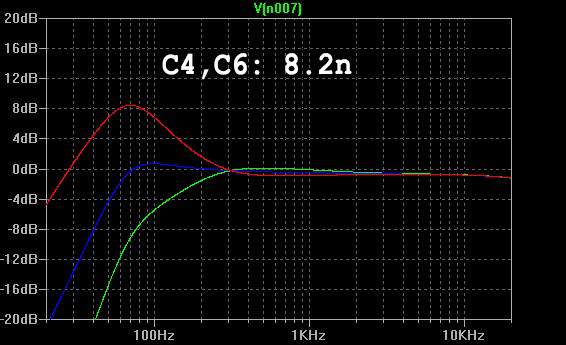
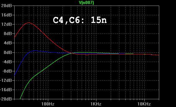
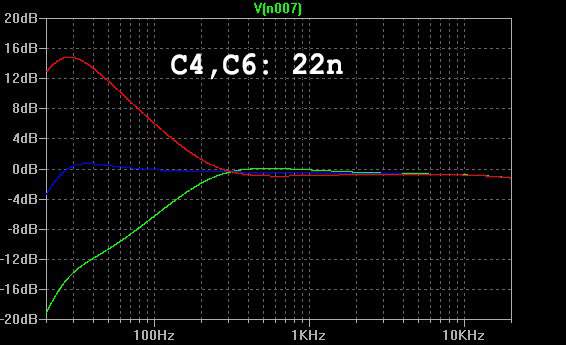
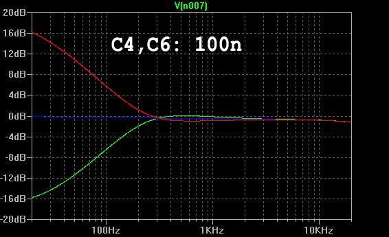
For those who find the built-in HPF too extreme, you can lower it by raising the value of the capacitors at C4 and C6.
The following graph show the bass pot at 0%, 50% (flat), and 100%.
The stock value of 8.2n sets the HPF at about 90Hz:
15n sets the HPF at about 50Hz:
22n sets the HPF at about 35Hz:
100n essentially takes out the HPF:
The following graph show the bass pot at 0%, 50% (flat), and 100%.
The stock value of 8.2n sets the HPF at about 90Hz:
15n sets the HPF at about 50Hz:
22n sets the HPF at about 35Hz:
100n essentially takes out the HPF:
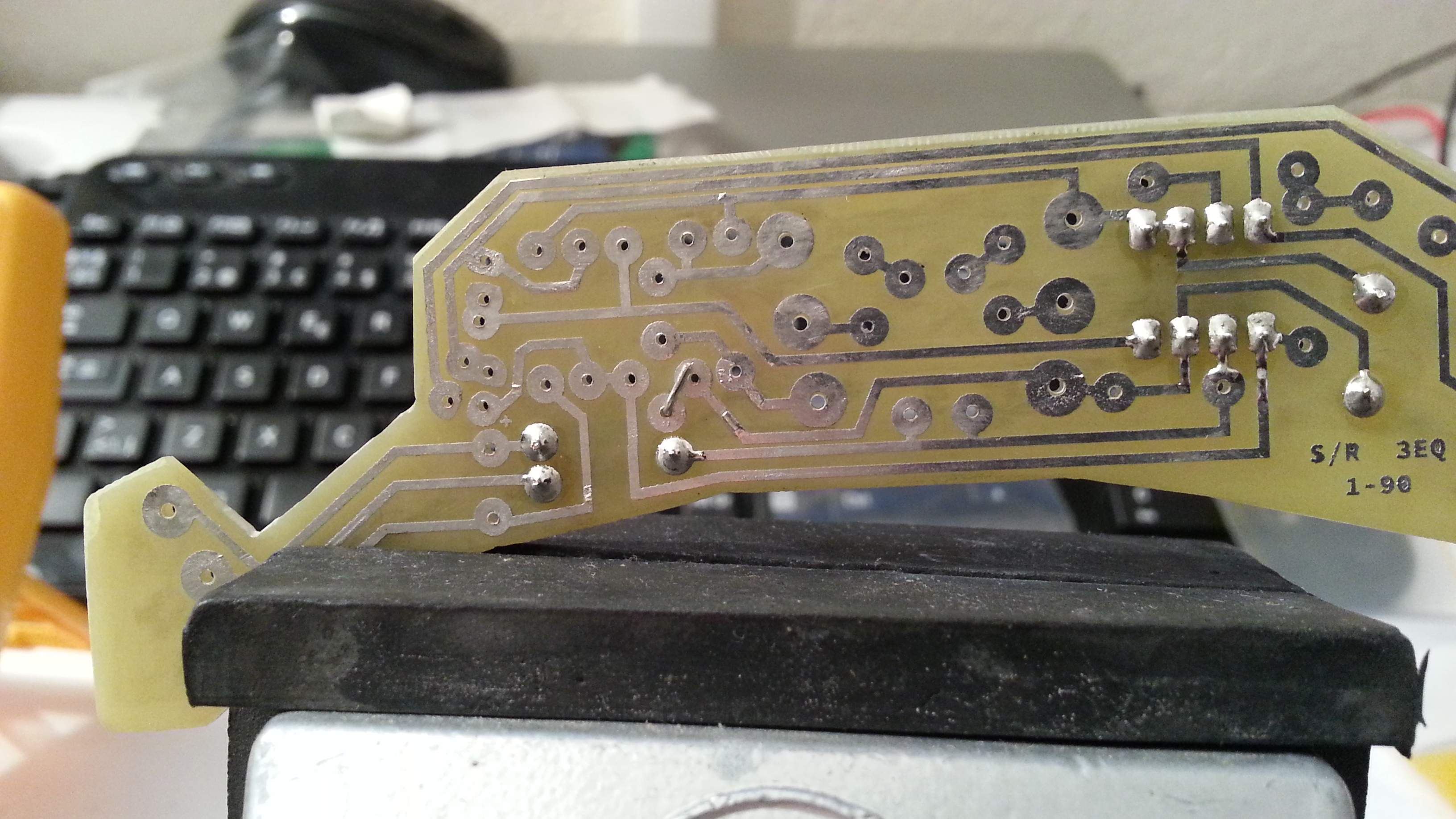
I found an error on the pcb I copied. I accidentally forgot to connect one side of R11. It's a very simple fix. Just bend that lead from R11 to R8 BEFORE soldering it.
good nights daniel
very good project, I've already started with the plate.
You work the circuit?
very good project, I've already started with the plate.
You work the circuit?
I'm waiting for the chromeplate to arrive. I had some bad luck with the first I ordered that didn't arrive. So I bought another one from another seller.
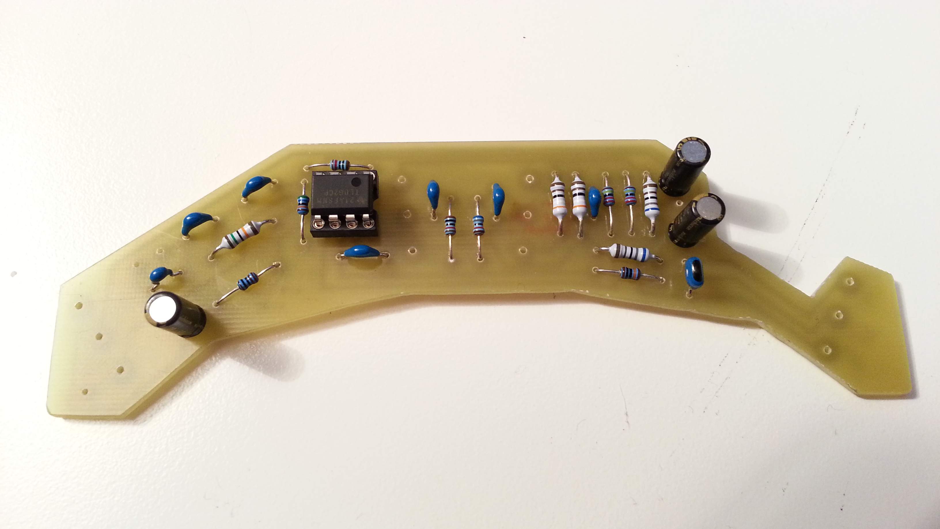
Everything is mounted on the pcb. I just need that chromeplate to mount all pots.
I haven't tested anything yet, but it all should work.
Everything is mounted on the pcb. I just need that chromeplate to mount all pots.
I haven't tested anything yet, but it all should work.

Good morning. So I see you've already mounted the circuit you work? I also manufactures and what does not work. habre done something wrong.
Julio, I have not tested it yet. I found a misstake I made on the PCB.
Did you apply this fix? Look at the first picture showing the solderside of the PCB where I bent over the pin from R11 to R8.
I found an error on the pcb I copied. I accidentally forgot to connect one side of R11. It's a very simple fix. Just bend that lead from R11 to R8 BEFORE soldering it.View attachment 479535 View attachment 479536
Did you apply this fix? Look at the first picture showing the solderside of the PCB where I bent over the pin from R11 to R8.
I've tested the preamp. I hooked it up to my original music man stingray as a pedal of sorts. I pulled the battery from my stingray and connected it to the preamp instead. All controls work.
Maybe slightly lower output, but I think that's because I didn't switch the preamps and just connected my clone in line.
Maybe slightly lower output, but I think that's because I didn't switch the preamps and just connected my clone in line.


