• TalkBass has been independent since 1998. Add your voice.
    Create a free account to reply to discussions, view embedded media, and browse with fewer display ads.
    Join freeLog in
    Want zero display ads or expanded classifieds tools? Compare plans.

Fender Preamp 0054137000 Response Curves

khutch

Praise Harp
Aug 20, 2011
4,140
1,821
suburban Chicago
There isn't any question here, just some information I am sharing in case someone looks for it later on. I have two active basses with the preamp in the title and I recently bought another one (another preamp that is) from the TB classifieds to put in another bass. The previous owner had parted out a Reggie Hamilton Standard Jazz. I know that he had had trouble getting the preamp to work right but I do not know if that is the reason he decided to part out the bass. I got the complete control plate with the active/passive switch and all the pots and knobs along with the preamp. As it turns out there is nothing wrong with any of it except for two things: the detent on the mid pot does not work, and the preamp does not have the dual section volume pot that a Reggie Hamilton preamp should have. As I received it the active/passive switch was only partially wired in and that along with the volume pot issue undoubtedly was the reason it was not working as expected. Evidently the TBer I bought it from had purchased the bass used from someone else and one of the previous owners must have made some modifications or repairs that were beyond his grasp. I hope that was not the reason for the part-out but the bottom line is that the measurements on the preamp that I just took should be representative of the breed. At one time the preamp was used in MIA as well as MIM basses but I've heard without verification that lately MIA basses use a different preamp.

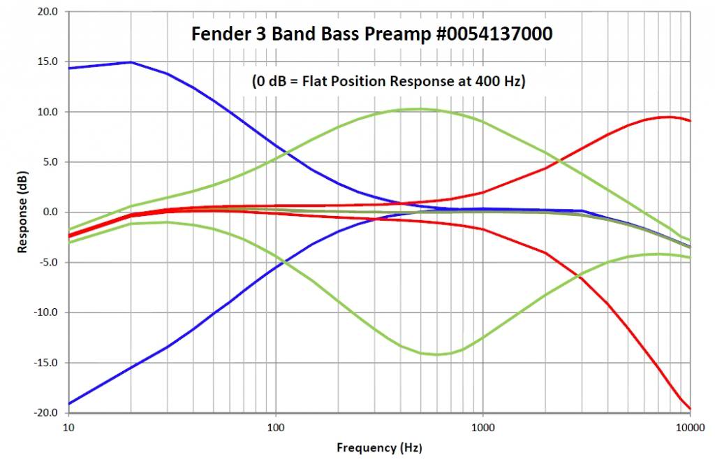
The chart below shows the frequency response of the preamp in the flat as well as all the cut/boost settings. This is the information I was curious about and since I had a preamp cut out from a bass it was easy to measure the response without disassembling anything. I measured it using a PicoScope 3206 digital oscilloscope that plugs into a USB port and uses your computer screen for the display. It has a signal generator output that can drive the preamp and even sweep the frequency if you like. Anyway the first chart below shows the conventional way preamp responses are presented. At each frequency point the response of the flat setting on the preamp was used as the 0 dB reference. It gives you a nice, neat plot that is useful even if it does not give you the whole picture.

FenderPreampChart1.jpg


This second chart shows the true frequency response. I never see plots like this on manufacturer's websites so I assume that they all use the type of plot above to convey the relative effect of the pot settings without complicating the results by including the corner frequencies on the preamp itself. As you can see below the preamp has both high and low frequency rolloff even when set to the flat position. In this case the corners are about 10 Hz and 10 kHz. For this plot the response at a single frequency chosen at random, 400 Hz, was used as the 0 dB reference.
FenderPreampChart2.jpg


The midband gain of the preamp in the flat position is 0 dB (ie, unity gain). I tried to measure the noise output but the noise on my DSO is higher than the preamp, it did not matter if I had the probe connected to the preamp or not, the noise was the same either way. The opamp in the preamp has a Texas Instruments logo and the model number 2062C so it is certainly a TI TLE2062C JFET input dual opamp. The input noise level is typically 40 nV/root-Hz which is middle of the road. You can get opamps that are at least 20 dB better - or worse. The current drain is 530 uA and significantly quieter opamps will generally draw more current than that. The pinout is standard for an 8 pin DIP dual opamp so you could swap in a quieter opamp if you wanted to trade some current for less noise. I've never found the noise level to be objectionable.

Well if you have always wanted to know more than what Fender tells you, there it is. Enjoy.

Ken
 
Good work! I just ran across this thread since I just picked up a late 90s Precision Deluxe, and have been Googling for info about the preamp. I'm glad to see that when set flat, it pretty much is in the frequency range I'd care about for a bass guitar.

Your plot does confirm one thing: The mid control's Q is massively wide. No wonder dialing it back sounds more like a volume control than a mid scoop.

The thing seems decent enough that I think I'm going to order the replacement mid pot. The one on my new bass is near death, and makes a horrible racket if its touched.
 
Some recent additions to this documentation. Below is a schematic "reverse engineered" from studying the PCB. Resistor values are printed on the components and part of the opamp part number is printed on it which allowed it to be tracked down. Most capacitor values are guesses based on changing the values in a circuit simulator until the results match the curves above reasonably well. The electrolytic capacitors have their values printed on them.

Preamp_Schematic_small.jpg


And then below is a photo of the circuit board if you want to attempt your own reverse engineering. The bottom side of the PCB shows the volume pot removed. This particular preamp board started life as a normal Fender preamp that had been grafted into a Reggie Hamilton Standard Jazz by a previous owner in place of the preamp that comes with that bass. The last owner of that bass decided to part it out because of this and other issues that unknown owner had caused and I bought it. I wanted the dual active/passive volume control that a "Reggie" preamp should have so I bought a replacement volume control and took these pictures after I had removed the original control and before I replaced it with the dual control. Also note that the bottom side photo of the preamp has been mirror imaged so that you can more easily trace out how the bottom side traces match up with the top side traces.


Preamp_Both.jpg


A word of caution. In their stringed instrument service diagrams Fender describes the preamps used in the Reggie Hamilton and their other active MIM and older MIA basses all with the same part number. However the Reggie's (and perhaps some MIA's) have a dual section volume pot where the other active MIMs I am familiar with have a single section pot. So, this part number does not seem to be a reliable guide to exactly what is on the pcb and may in fact only be the part number for the pcb itself. The circuit diagram above predicts a gain of 2 and I measure a gain of 2 on this particular preamp but I am pretty sure I once measured a gain of 1 on my Reggie preamp so there could be other minor variations in component values from model to model in spite of the identical part numbers.

Also, I am an electrical engineer and I follow current engineering practice of denoting capacitor values in nF (nano-Farads) rather than the common musician practice of using fractional uF (micro-Farads). So you will see 1n, 2.2n, 6.8n, 22n, 47n, and 470n capacitor values in the schematic above. You may call these 0.001u, 0.0022u, 0.0068u, 0.022u, 0.047u and 0.47u respectively.
 
Last edited:
  • Like
Reactions: Malafaia
I don't really know since this is the only one I have ever dissected. I owned an Ibanez SR505 for a while and it had a different preamp with a switch selectable mid-band frequency but otherwise it was probably similar to this one. I can tell you that some preamps have a non-flat response when you set the knobs to the "flat" position to give them a characteristic sonic color. And I know that a few preamps are advertised as having very non-typical responses or circuit topologies. But I can't really even tell you if there is such a thing as a "typical" bass guitar preamp. This one is a standard Baxandall circuit.
 
Some recent additions to this documentation. Below is a schematic "reverse engineered" from studying the PCB. Resistor values are printed on the components and part of the opamp part number is printed on it which allowed it to be tracked down. Most capacitor values are guesses based on changing the values in a circuit simulator until the results match the curves above reasonably well. The electrolytic capacitors have their values printed on them.

View attachment 578076

And then below is a photo of the circuit board if you want to attempt your own reverse engineering. The bottom side of the PCB shows the volume pot removed. This particular preamp board started life as a normal Fender preamp that had been grafted into a Reggie Hamilton Standard Jazz by a previous owner in place of the preamp that comes with that bass. The last owner of that bass decided to part it out because of this and other issues that unknown owner had caused and I bought it. I wanted the dual active/passive volume control that a "Reggie" preamp should have so I bought a replacement volume control and took these pictures after I had removed the original control and before I replaced it with the dual control. Also note that the bottom side photo of the preamp has been mirror imaged so that you can more easily trace out how the bottom side traces match up with the top side traces.


View attachment 578077

A word of caution. In their stringed instrument service diagrams Fender describes the preamps used in the Reggie Hamilton and their other active MIM and older MIA basses all with the same part number. However the Reggie's (and perhaps some MIA's) have a dual section volume pot where the other active MIMs I am familiar with have a single section pot. So, this part number does not seem to be a reliable guide to exactly what is on the pcb and may in fact only be the part number for the pcb itself. The circuit diagram above predicts a gain of 2 and I measure a gain of 2 on this particular preamp but I am pretty sure I once measured a gain of 1 on my Reggie preamp so there could be other minor variations in component values from model to model in spite of the identical part numbers.

Also, I am an electrical engineer and I follow current engineering practice of denoting capacitor values in nF (nano-Farads) rather than the common musician practice of using fractional uF (micro-Farads). So you will see 1n, 2.2n, 6.8n, 22n, 47n, and 470n capacitor values in the schematic above. You may call these 0.001u, 0.0022u, 0.0068u, 0.022u, 0.047u and 0.47u respectively.
Great job!
 
Great job!

I agree. This is a nice post from Ken. Tracing a surface mount circuit is a very tedious gig!

the dual section volume pot that a Reggie Hamilton preamp should have. As I received it the active/passive switch was only partially wired in and that along with the volume pot issue undoubtedly was the reason it was not working as expected.

I wanted the dual active/passive volume control that a "Reggie" preamp should have so I bought a replacement volume control

That's a nice idea, and yeah almost certainly why the original owner, (as mentioned in Ken's original post), couldn't fathom replacing the volume pot. I'd love to know who come up with this - Reggie's tech? a fender guy? Reggie himself?

FWIW, years ago I also came up with it! And I have used it in several active/passive basses over the years. And I was pretty proud of my brainwave, until I stumbled on a genuine fender spare part listing that has 250K/25K dual gang pot. Oh well. There's nothing new under the sun... I used to mod a pot to get it working.

It means you have the volume pot at the output of the pre in active mode (25K), but then in passive mode, it switches to the 250K.


As for the response curves. Yeah the mid control is pretty limited in these designs. AFAICT, the idea of 3 filters wrapped around a single opamp comes from 80's hifi circuits. I've seen this topology in many many preamp designs. The 3-band MM pre is very similar. These days, you'd use a separate opamp, possibly also a gyrator, to get more peaky mid control response.
 
C9 connects to the bass pot so it is unlikely to affect the treble! R4, R7 - R10, C6, C7, and the treble pot form the treble circuit. If there is an issue with the treble it is likely to be there. Note that the capacitor values were deduced from making a circuit simulation match the measured response so there is some margin for error there.

No, I do not know where you can buy these. People who sell Fender parts may have them but I would suppose that this model has been replaced by a new version by now.
 
Thanks for your answer. I know that this capacitor C9 is not in the treble branch and can only affect bass. But it looks like passive circuit, it can interfere with treble ?!

Regarding the components, they are quite common but we must find which is down
 
The circuit is an active circuit, all three bands have feedback from the output through their respective adjustment pots. There is some interaction between the bands. Increasing C9 from 470nF to 470uF in a simulation does increase the bass boost/cut by 1-2 dB but it has little effect on the treble and mid bands. Decreasing C9 from 470nF to 470fF essentially kills the bass boost/cut completely and extends the midband response by about a decade in the low frequency direction and adds about 5dB to the boost and cut. The treble response gains about 5dB of boost and cut and lowers in frequency slightly.
 
@khutch

thanks a lot for sharing bro. That's really brilliant work.

C5 on the pre-amphasize filter at U1a reads 4.7uF. Is this right?
I did a quick and dirty run in LTspice and get a meaningfull pre-emphasize response with 4.7nF for C5.
Just asking.