...a series/parallel switch. I think I'm hooked!
Apologies in advance for pic quality but all I had was my phone and I wasn't about to break the flow of the project to hunt down anything better... was already on a tight timeline!
Anyway, in my ongoing quest to know thing off of my 'to do' list, I finally got round to jumping on a project that has been waiting in the wings nearly as long as I have been playing my first bass. Here's the skinny, and it started here:
1-1 by Saxn75, on Flickr
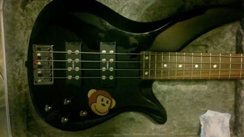
That's a Yamaha RXB374, an active bass with master volume, pickup blend, and bass/treble boost and cut controls. It has been a pretty good player, but I have always had the sneaking suspicion that she could do a bit better. After doing a fair amount of research, I decided to mod it up a little with an active to passive conversion... because to be honest I invested in a pretty nuce bass amp and I just KNEW that the preamp on that would absolutely destroy the one built into my Yammy in terms of sound quality, noise floor, etc. So finally two days ago the day came, and I went to the local music joint and picked up four 250k pots for the conversion. I rescued a couple of capacitors (.024 uF) from a defunct PA system to use for the tone controls and went to work.
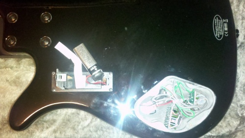
Taking a look at the back:
2-1 by Saxn75, on Flickr
You can see all the crap that has to come out. As I began gutting the poor girl I realized that I now had an empty battery compartment to work with... and I ALSO had a mini DPDT toggle switch in the junk drawer... hmmmm.... a plan began forming. I now envisioned an active/passive conversion, with independent pickup volume and tone controls, running to a series/parallel switch. Tone options for DAYS!
So I ripped out her innards...
4-1 by Saxn75, on Flickr
And took off the pickups...

5-1 by Saxn75, on Flickr
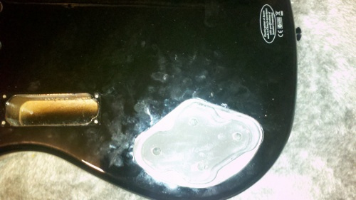
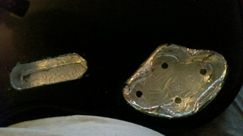
And saw that not only was the battery compartment not shielded at all (to be expected) but that Yamaha had shielded the pickup and electronics cavities with a conductive paint of some sort, but due to a poor choice of material, inadequate coating, or both I did not believe (and STILL don't believe) that the EMI shielding was adequate, so I decided to add in the step of beefing that up a little bit. I used aluminum tape for this and wound up with the following:

7-1 by Saxn75, on Flickr
6-1 by Saxn75, on Flickr
All grounds checked good, so on we go.
I also ran into a bridge grounding issue that I WISH had taken photos of and sent to Yamaha QC, but I didn't. Let's just say it was no wonder that the amp popped every time I put my fingers on the strings! All fixed now though...
I had to do some drilling to get the pots in, but that was a minor diversion, and after fitting the pots and the "afterthought" series/parallel switch into place I began the long process of soldering and insulating... BLEH! The single most tiring part of the ordeal summed up in the following two pics:

9-1 by Saxn75, on Flickr

10-1 by Saxn75, on Flickr
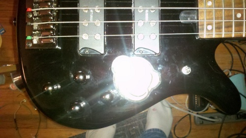
She was ready to test, and after a short stint playing on a single string I found two minor gremlins in the works, one in the neck pickup and one in the hot line to the output jack... both of which were the result of getting in a hurry and not following mil-spec soldering protocol! I will confess: I didn't tin the wire and that allowed stray copper strands to bridge the circuit and short it out. There, I said it. But once that was all squared away, I had a brand new PASSIVE Yamaha...with independent volume and tone controls to boot! She don't look dramatically different:
11-1 by Saxn75, on Flickr
But she plays a treat AND I am proud to say that she's a lot quieter between tunes! Looking forward to gigging it soon.
And now on to the next thing on the list...
EDIT: Yeah, I know there's a hole in my sock. My grandma would be devastated. Sorry.
Apologies in advance for pic quality but all I had was my phone and I wasn't about to break the flow of the project to hunt down anything better... was already on a tight timeline!
Anyway, in my ongoing quest to know thing off of my 'to do' list, I finally got round to jumping on a project that has been waiting in the wings nearly as long as I have been playing my first bass. Here's the skinny, and it started here:
1-1 by Saxn75, on Flickr
That's a Yamaha RXB374, an active bass with master volume, pickup blend, and bass/treble boost and cut controls. It has been a pretty good player, but I have always had the sneaking suspicion that she could do a bit better. After doing a fair amount of research, I decided to mod it up a little with an active to passive conversion... because to be honest I invested in a pretty nuce bass amp and I just KNEW that the preamp on that would absolutely destroy the one built into my Yammy in terms of sound quality, noise floor, etc. So finally two days ago the day came, and I went to the local music joint and picked up four 250k pots for the conversion. I rescued a couple of capacitors (.024 uF) from a defunct PA system to use for the tone controls and went to work.
Taking a look at the back:
2-1 by Saxn75, on Flickr
You can see all the crap that has to come out. As I began gutting the poor girl I realized that I now had an empty battery compartment to work with... and I ALSO had a mini DPDT toggle switch in the junk drawer... hmmmm.... a plan began forming. I now envisioned an active/passive conversion, with independent pickup volume and tone controls, running to a series/parallel switch. Tone options for DAYS!
So I ripped out her innards...
4-1 by Saxn75, on Flickr
And took off the pickups...
5-1 by Saxn75, on Flickr
And saw that not only was the battery compartment not shielded at all (to be expected) but that Yamaha had shielded the pickup and electronics cavities with a conductive paint of some sort, but due to a poor choice of material, inadequate coating, or both I did not believe (and STILL don't believe) that the EMI shielding was adequate, so I decided to add in the step of beefing that up a little bit. I used aluminum tape for this and wound up with the following:
7-1 by Saxn75, on Flickr
6-1 by Saxn75, on Flickr
All grounds checked good, so on we go.
I also ran into a bridge grounding issue that I WISH had taken photos of and sent to Yamaha QC, but I didn't. Let's just say it was no wonder that the amp popped every time I put my fingers on the strings! All fixed now though...
I had to do some drilling to get the pots in, but that was a minor diversion, and after fitting the pots and the "afterthought" series/parallel switch into place I began the long process of soldering and insulating... BLEH! The single most tiring part of the ordeal summed up in the following two pics:
9-1 by Saxn75, on Flickr
10-1 by Saxn75, on Flickr
She was ready to test, and after a short stint playing on a single string I found two minor gremlins in the works, one in the neck pickup and one in the hot line to the output jack... both of which were the result of getting in a hurry and not following mil-spec soldering protocol! I will confess: I didn't tin the wire and that allowed stray copper strands to bridge the circuit and short it out. There, I said it. But once that was all squared away, I had a brand new PASSIVE Yamaha...with independent volume and tone controls to boot! She don't look dramatically different:
11-1 by Saxn75, on Flickr
But she plays a treat AND I am proud to say that she's a lot quieter between tunes!
Looking forward to gigging it soon.And now on to the next thing on the list...
EDIT: Yeah, I know there's a hole in my sock. My grandma would be devastated. Sorry.


 I hate useless bits hanging around on anything, and right now that's exactly what I have.