• TalkBass has been independent since 1998. Add your voice.
    Create a free account to reply to discussions, view embedded media, and browse with fewer display ads.
    Join freeLog in
    Want zero display ads or expanded classifieds tools? Compare plans.

GK rails in a pedal?

John. If you are still hearing a lot of that fizzy static sound, try a 47pF or 100pF cap in C4.

What I believe is happening is that that fizzy sound from the clipping happens on the real GK amp also. But on the real GK amp the output levels are over 100Vp-p and your amp less than 20Vp-p, so if the fizzyness stays at the same amplitude, you will hear more of it in your amp sim because of the reduced ratio. Then you are amplifying it more with your bass amp, so it stands out more.

U1a is trying desperately to keep the output exactly like the input, but only larger. When the output drivers clip, U1a is outputting large error correction signals. Just at the point of clipping, this error correction causes a tiny bit of oscillation at the peaks (sounds like static). Changing C4 to a larger value slightly rolls off the HF response of the amp, but it also speeds up the error correction from U1a a bit and reduces that oscillation.

-Frank
 
  • Like
Reactions: ryansalmond
okay, thanks for the tip. I was going to raise the value of C4 in my other builds to see if it helped but since i'm now building the V5 version, I probably won't bother on the others.

Yeah, keep those others original. The Smithsonian Museum may call you so that they can display them next to the Darwin exhibit of monkey to man.:D

-Frank
 
  • Like
Reactions: ryansalmond
BTW, the 400RB is probably the best GK amp knon for its 'driven on the rails' tone but the 700RB is great too.

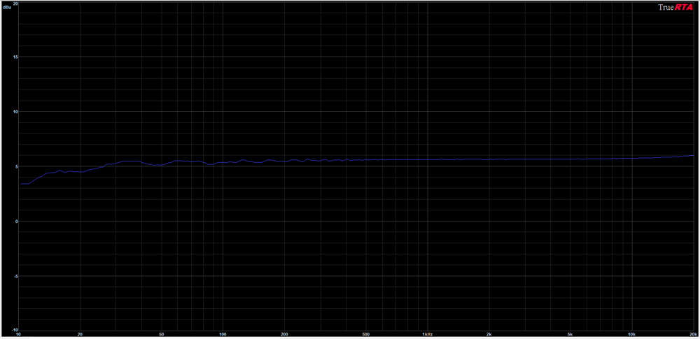
here's my RTA result for the TY250P (and it looks GREAT!
TY250Pfreqtest.jpg


Hey John. After testing the TY250 with my power amp yesterday, I had a pretty novel idea on a cool use for this thing. When you get a chance, please run this RTA test again with a 1K load across the secondary coil. The two TY250's I have can handle a 1K load and I want to be sure yours can also.

After we get this GK amp sim working nicely, I will show you this idea that I have.

-Frank
 
okay, i'll try that when I get back from running a few errands...........


BTW, my V5 fired up and works perfectly with no issues (YAY!) .
I can't really hear the hi-cut switch's effect on it thru my amp and tweeterless Eminence 215 cab but i'll run some TrueRTA and scope tests on it too.

here's a pic of the V5 PCB:

0001-GK_V5PCB-02.jpg
 
okay, i'll try that when I get back from running a few errands...........


BTW, my V5 fired up and works perfectly with no issues (YAY!) .
I can't really hear the hi-cut switch's effect on it thru my amp and tweeterless Eminence 215 cab but i'll run some TrueRTA and scope tests on it too.

here's a pic of the V5 PCB:

0001-GK_V5PCB-02.jpg

Nice job!

BTW, would the 4 output transistor version (V4) sound different than the 2 output transistor version (V5) or is it just my imagination?

The V4 only had two output transistors, the other two were foldback clippers. With the foldback switched off, those other two transistors were essentially out of the circuit. The changes that may have an impact on the sound are the new front-end, the new HF filter caps C15 and C16, and C14/R27. Everything else should be the same as your last modified V4.

-Frank
 
  • Like
Reactions: ryansalmond
BTW, so far I like it better with a 100p for C4. i'm going to try it with a 150p and 220p next but they might be too much.
for some reason it seems to be a little brighter than the V4 (whereas with those caps, I would've thought that it would be darker!)
BTW, there's absolutely NO STATIC or surging on the input level pot now. :thumbsup:
 
BTW, so far I like it better with a 100p for C4. i'm going to try it with a 150p and 220p next but they might be too much.
for some reason it seems to be a little brighter than the V4 (whereas with those caps, I would've thought that it would be darker!)
BTW, there's absolutely NO STATIC or surging on the input level pot now. :thumbsup:

Great news!

One other thing that maybe, very slightly change the tone a tiny bit are the heavy filters you now have on the U1 power pins. I don't think they are, because I have done this many times, but they are also new in this circuit.

-Frank
 
If you go too much larger with C4, we might have to adjust the value of the Miller cap C6 around Q4.

C4 will affect global feedback of the amp, whereas C6 just affects feedback around the Q4 amplifier. They both affect the frequency response seen at the output, but because they are two poles within the circuit negative feedback loop, increasing C4 much more than 100pF may INCEREASE the HF response... just the opposite of what you would think would happen.

I will have to run simulations to know for sure.

-Frank
 
If you go too much larger with C4, we might have to adjust the value of the Miller cap C6 around Q4.

C4 will affect global feedback of the amp, whereas C6 just affects feedback around the Q4 amplifier. They both affect the frequency response seen at the output, but because they are two poles within the circuit negative feedback loop, increasing C4 much more than 100pF may INCEREASE the HF response... just the opposite of what you would think would happen.

I will have to run simulations to know for sure.

-Frank

Making C4 larger will not increase the freq response within this circuit and it has a gradual affect on the roll-off. But increasing C6 pulls some of those high freq's back and then causes the roll-off to be much steeper.

Try 150pF for C4 and 470pF for C6. The -3dB point will be about 10KHz, but the roll-off slope is much steeper. With this combo you will have to change C15/C16 values to have them heard.

-Frank