• TalkBass has been independent since 1998. Add your voice.
    Create a free account to reply to discussions, view embedded media, and browse with fewer display ads.
    Join freeLog in
    Want zero display ads or expanded classifieds tools? Compare plans.

HELP! Re-Wiring Eden 410XLT cab!!

Mar 26, 2013
917
1,824
Okay fellas, I need some help here. Finishing a rig to donate to my church.
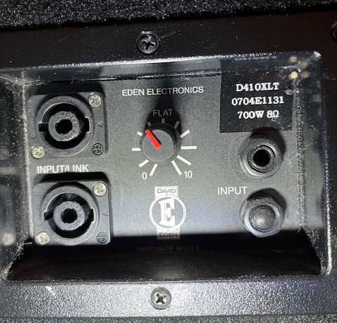
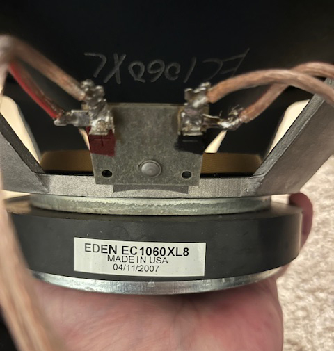
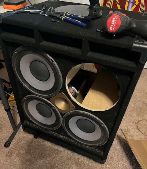
Picked up an Eden 410XLT with a busted speaker. [Shout out to The Speaker Exchange in Tampa, Florida!!! They did a quick turn-around on this speaker recone!]

I need help re-wiring it.
1.jpg


0.jpg

3.jpg

2.jpg

4.jpg


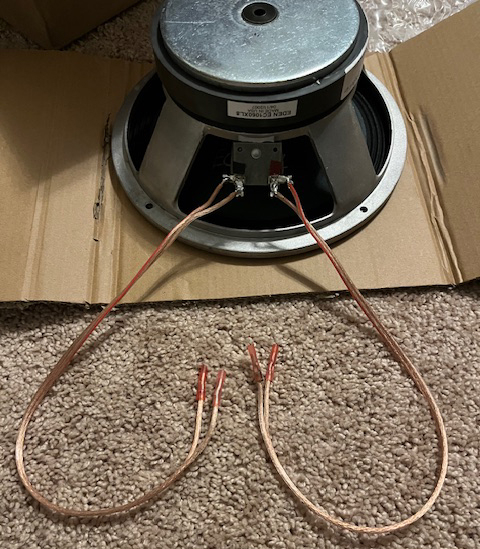
I was in a rush to leave town, headed to a conference (and The Speaker Exchange!] in Tampa, so I pulled the offending speaker and BLINDLY pulled the wires with slip-on connectors and clipped the wires that were soldered. I know. Also, no before-pictures.

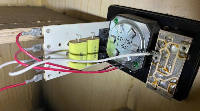
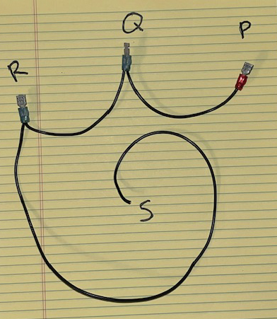
This is the wire that came off of the Xover,
noted P, Q, R, & S:
6.jpg

5.jpg


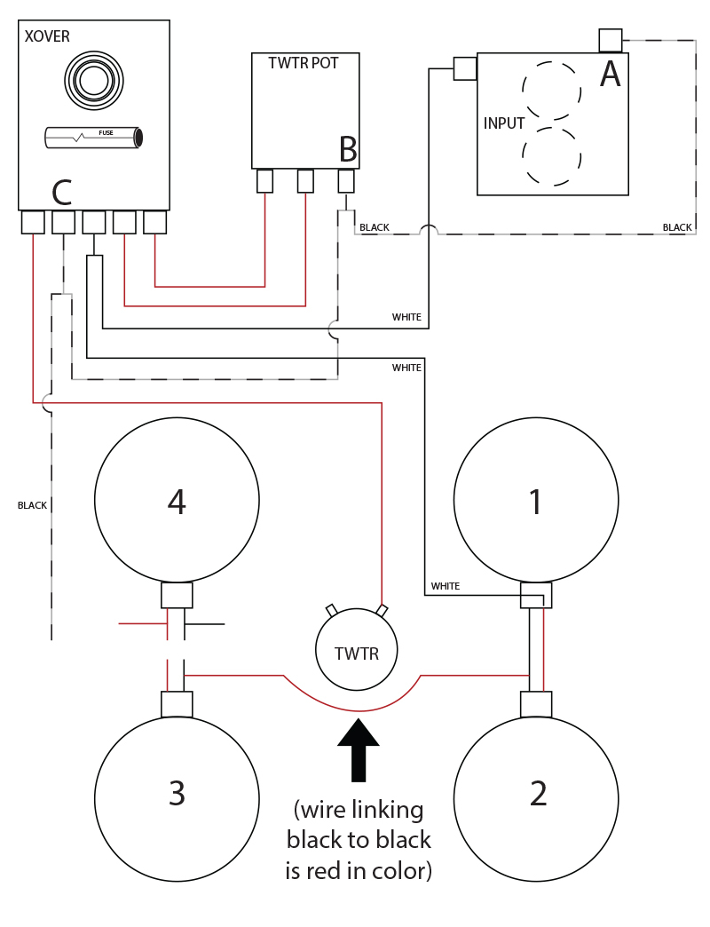
I made a very rudimentary wiring diagram in Illustrator:
7.jpg


Connector Q appears to only fit slip-on tab B.

Is it the case that P will slip-on to tab A, that Q will slip-on tab B, that R will slip-on tab C, and the bare-end S will go to negative on Speaker 4?

Then Speaker 4 negative jumps to tweeter?

And Speaker 4 positive jumps to Speaker 3 positive?

*** The dotted line in my rudimentary diagram represents the Xover wire PQRS, and where I believe it goes ***

I can’t afford to screw this up, so I appreciate the help!!!

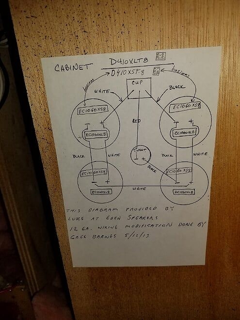
I do already have this diagram, but as you can see, the wiring coming from the “cup” is rudimentary enough that my inexperienced eye can’t properly divine what goes where.
0b0fb3a84e442954b2a51b80c376fe19.jpg


Thank you in advance, TB family, for all your help on this!

(And thank you, again, to @2saddleslab for the generous deal on the head unit for this rig!!)

(quick disclaimer: I know that if one speaker is jacked, the others are likely jacked. It’s okay, I’m willing to repair the other speakers)


Help!
 
Last edited:
  • Like
Reactions: 2saddleslab
At this point, with the wiring mess that you already have, your best and safest bet it to properly rewire it (using proper 16 or 18 gauge speaker hookup wire and faston connectors).

What you have is an example of a DYI upgrade/modification gone wrong IME.
 
Not sure how to help you as the hand-drawn diagram is pretty clear on how the drivers are connected. The woofers are connected in parallel-series and the tweeter is connected in reverse polarity.

This shows the difference between parallel/series and series/parallel.

1770485589106.png


Regarding the rest of the connections, here's a diagram that may help:
1770484926355.png

Note the tweeter in this diagram is not connected in reverse polarity, which is probably wrong :bag: . You an use your ears, or go with reverse polarity per the factory drawing. IME it probably won't make much of a difference.

Notice the woofers are essentially connected directly to the input jack; so they run full range. The tweeter is connected to an L-Pad, fuse and high pass filter network.

The circuit should be very similar to what is shown here, except the SWR woofers are wired in series parallel. Notice the tweeter is wired in reverse polarity on the SWR schematic just like on the hand drawn Eden diagram.


I suggest comparing the connection in the SWR circuit to the terminals of the Eden network. Probe the connections with a multi-meter to confirm they are correct.

Edited to sub in the parallel series woofer connections and flip the polarity on the tweeter

1770486868052.png


I would connect the woofers and then do a 9V battery check. The woofers should all move out if you match + and - terminals of the drivers to the + and - terminals of the battery.

Sorry if this is confusing...it's the best I can do.
 
At this point, with the wiring mess that you already have, your best and safest bet it to properly rewire it (using proper 16 or 18 gauge speaker hookup wire and faston connectors).

What you have is an example of a DYI upgrade/modification gone wrong IME.
@agedhorse if I rewire it according to the schematic I drew out and the clarifying questions I posed - with proper gauge speaker wire - I am good to go?
 
Last edited:
Not sure how to help you as the hand-drawn diagram is pretty clear on how the drivers are connected. The woofers are connected in parallel-series and the tweeter is connected in reverse polarity.

This shows the difference between parallel/series and series/parallel.

View attachment 7427454

Regarding the rest of the connections, here's a diagram that may help:
View attachment 7427447
Note the tweeter in this diagram is not connected in reverse polarity, which is probably wrong :bag: . You an use your ears, or go with reverse polarity per the factory drawing. IME it probably won't make much of a difference.

Notice the woofers are essentially connected directly to the input jack; so they run full range. The tweeter is connected to an L-Pad, fuse and high pass filter network.

The circuit should be very similar to what is shown here, except the SWR woofers are wired in series parallel. Notice the tweeter is wired in reverse polarity on the SWR schematic just like on the hand drawn Eden diagram.


I suggest comparing the connection in the SWR circuit to the terminals of the Eden network. Probe the connections with a multi-meter to confirm they are correct.

Edited to sub in the parallel series woofer connections and flip the polarity on the tweeter

View attachment 7427466

I would connect the woofers and then do a 9V battery check. The woofers should all move out if you match + and - terminals of the drivers to the + and - terminals of the battery.

Sorry if this is confusing...it's the best I can do.
The drivers aren’t the challenging part, it’s just ensuring that I connect all the wires correctly…specifically from xover to tweeter
 
@agedhorse if I rewire it according to the schematic I drew out and the clarifying questions I posed - with proper gauge speaker wire - I am good to go?
Even if you get all the connections perfect, you may not get the desired results. Why? All four of the drivers need to be healthy and match. Here are some possibilities:
1. Since one driver has failed, it would not be unusual for some or all of the other three drivers to have experienced similar damage.
2. AFAIK there have not been authentic recone kits for the factory drivers for many years, and there is no guarantee an after-market recone kit will comply tightly with the original specs.

Let's keep our fingers crossed ;).

The A to B to C connections appear to match what I am proposing. Were any of these connections left in place? If not, it would be a good idea to do some measurements with a mult-meter to make sure the order of connections on the crossover card have not been reversed.

IMHO double check your work and do the battery check on the woofers before you hook up the tweeter.

Assuming black is negative and red is positive, I believe the diagram you started has some errors. For example the jumper on the bottom is connected from black (-) to black (-). It should be connected from + to -, but which side is which depends the polarity of the connections to speaker #1 and #4 from the input jack.

To match the original Eden diagram, the white wire (positive) should be connected to the positive terminal of speaker #4, rather than speaker #1. This is not technically wrong, but it could cause confusion that leads you to connect something else incorrectly such as the jumper discussed above. You can leave the white wire connected to (+) of #1 as long as you connect the black wire to the (-) of #4 and also connect the jumper properly.
 
Even if you get all the connections perfect, you may not get the desired results. Why? All four of the drivers need to be healthy and match. Here are some possibilities:
1. Since one driver has failed, it would not be unusual for some or all of the other three drivers to have experienced similar damage.
2. AFAIK there have not been authentic recone kits for the factory drivers for many years, and there is no guarantee an after-market recone kit will comply tightly with the original specs.

Let's keep our fingers crossed ;).

The A to B to C connections appear to match what I am proposing. Were any of these connections left in place? If not, it would be a good idea to do some measurements with a mult-meter to make sure the order of connections on the crossover card have not been reversed.

IMHO double check your work and do the battery check on the woofers before you hook up the tweeter.

Assuming black is negative and red is positive, I believe the diagram you started has some errors. For example the jumper on the bottom is connected from black (-) to black (-). It should be connected from + to -, but which side is which depends the polarity of the connections to speaker #1 and #4 from the input jack.

To match the original Eden diagram, the white wire (positive) should be connected to the positive terminal of speaker #4, rather than speaker #1. This is not technically wrong, but it could cause confusion that leads you to connect something else incorrectly such as the jumper discussed above. You can leave the white wire connected to (+) of #1 as long as you connect the black wire to the (-) of #4 and also connect the jumper properly.
Yeah, the jumper wire is red in color, I assumed someone ran out of wire. It does jump from black to black.
All of the other wiring is still in place, only A, B, & C were pulled (by me).

I will take all of your above recommendations on this project. Awesome!

As it turns out, there is (tiny, but) visible damage to two of the other speakers, and I suspect they've been reconed before (after taking off the grille, I can see stripping in the screws of the other three speakers.)

But hey, I got the cab for the labor of loading it up and taking it away. So if I end up reconing the other three speakers altogether, that's about $600 bucks for a 700 watt 4x10 Eden XLT that will likely never be pushed anywhere near it's limits!
I'll take that.
 
  • Like
Reactions: Wasnex
Yeah, the jumper wire is red in color, I assumed someone ran out of wire. It does jump from black to black.
Using red for the jumper is not a surprise or unusual AFAIK. Ideally I would like to see a different color for the jumper, but that would be more expensive, so it's usually not done.

If color coding is not used consistently you can't rely on it. Instead, you have to go by the polarity of the connections and pretty much ignore the color of the wires. FYI assuming the driver are hooked up in parallel series: If both sides of the jumper are connected to a negative speaker terminal, only two of drivers will be powered.
 
At this point, with the wiring mess that you already have, your best and safest bet it to properly rewire it (using proper 16 or 18 gauge speaker hookup wire and faston connectors).

What you have is an example of a DYI upgrade/modification gone wrong IME.
This...I bought a Eden Metro years ago in a pawn and one connection was barely hanging on...I always check connections and impedance immediately.
 
Using red for the jumper is not a surprise or unusual AFAIK. Ideally I would like to see a different color for the jumper, but that would be more expensive, so it's usually not done.

If color coding is not used consistently you can't rely on it. Instead, you have to go by the polarity of the connections and pretty much ignore the color of the wires. FYI assuming the driver are hooked up in parallel series: If both sides of the jumper are connected to a negative speaker terminal, only two of drivers will be powered.
I used to take a black marker and mark what I knew was the negative wire! I did the same with speakers putting a black dot by the negative terminal....but some speakers are reverse polarity to add to the 😠 madness so yes check with a 9 volt battery, very briefly touch the terminals to 👍 confirm.
 
Make sure all speakers are the same impedance, keep polarity consistent + to +, – to – and you should be good.
Not for series wiring... be aware that polarity APPEARS different for series versus parallel wiring.
 
SO… in order:
#1: you were all incredi-helpful.
#2: remember when you all warned me that ALL the speakers might be blown if the first one was blown at high wattage/high volume?
$400 into shipping and (fantastic) re-coning jobs by Speaker Exchange in Tampa… it’s now clear the other two are blown. In that insidious, ‘not-fully-separated-anywhere-around-the-baffle and not visually damaged sort of way’ sort of blown.
The two replaced speakers are tight and awesome, the two remaining sound like a fuzz pedal soldered by a three year old.
Lesson learned.
If only you’d all have told me.
Which… you did.