• TalkBass has been independent since 1998. Add your voice.
    Create a free account to reply to discussions, view embedded media, and browse with fewer display ads.
    Join freeLog in
    Want zero display ads or expanded classifieds tools? Compare plans.

Help with cab / driver modeling

I'm going to upgrade a Fender Rumble 100 Combo with a Celestion BN12-300S (4) - [Yes the original driver is 4 Ohm as well.].

Here are the details:
Celestion BN12-300S (4)
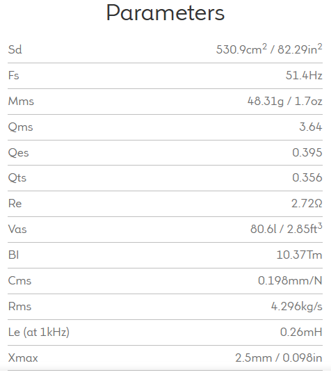
1753072892869.png


Box Properties:
Internal Volume: 1.3 Cu. ft
Two Ports: 3" diameter x 2.25" length
_________________________________________


The main question is what does the frequency response look like and would different length ports help the overall tone for a BEADG 5 string bass guitar?

The previous owner added a bit of acoustic lining treatment inside the cab, but I haven't looked inside the cabinet yet, so see which sides / back have treatment.

From what I remember from reading some R100c mod threads, leaving 2 adjacent sides lined or only partially lined yields a better balance without excessive dampening of the overall tone.

Thank you in advance!

P.S. Thank you, @Wasnex for consolidating the above info from another thread of mine!

 
When I was last experimenting with a cab I was surprised by how little port length changes seemed to impact the perceived tone. I couldn't really tell the difference. Changes to the amount of of damping material, on the other hand, made a huge difference to what I heard. That was a standard EADG bass though, YMMV, but I suggest you'll want to pay a lot of attention to the lining side of it.
 
When I was last experimenting with a cab I was surprised by how little port length changes seemed to impact the perceived tone. I couldn't really tell the difference. Changes to the amount of of damping material, on the other hand, made a huge difference to what I heard. That was a standard EADG bass though, YMMV, but I suggest you'll want to pay a lot of attention to the lining side of it.
I suspect that the effect that port length changes have, mostly depends on what driver that you are changing from and changing to - less for some drivers and more for others.
 
I suspect that the effect that port length changes have, mostly depends on what driver that you are changing from and changing to - less for some drivers and more for others.
I'll share what I think I know. Hopefully it's reasonably correct.

The dimensions of the port tune the cab to a certain frequency. The cab is essentially a Helmholtz resonator. There are two port dimensions, area and length. Make the area of the port bigger and the tuning goes higher. Make the port longer and the tuning goes lower.

Internal volume of the cab is a factor. Increase the volume and the tuning goes lower.

The driver has a Fs (resonance in free air). When placed in a sealed cab, the driver resonance will be modified to Fc. The specific frequency of Fc is dependent on both the driver's characteristics and the internal volume of the cab. However, Fc is always higher the Fs. In sealed cabs, driver response drops below Fc.

Ported cab acts pretty much like a sealed cabs for frequencies that are well above the tuning frequency Fb. As the frequency drops and approaches Fb, the port starts to become active. The port is tuned to become active as the driver begins to cut off. There are different ways to align the cab's tuning in relation to the driver's cut off. This is why modeling is so important.


As the port become active it start to produce sound. It also starts to suppress the driver's cone excursion. At Fb, the port is providing most of the system's output and also providing maximum suppression of cone excursion . Below Fb two things happen: 1. System output drops quickly, 2. Driver excursion increases rapidly.

The resultant excursion plot for a driver in a ported design is S shaped. Here an excursion plot for a model of a subwoofer using an Eminence 3015LF

1754538625121.png


1754538686052.png


Take a look at the graph and consider these facts.
1. Fb is 38hz. This is where the port is providing most of the sound and providing max suppression to cone excursion. Notice that driver excursion is dipped at this frequency.
2. Xmax = 0.378" or 9.6mm. The plot shows that driver excursion peaks between 50hz and 60hz, before dipping as the frequency approaches Fb. In many designs, excursion approaches Xmax during this peak; however not with this particular design.
3 As the frequency drop below Fb of 38hz, excursion increases fairly quickly to 9.6mm. when the trace exceeds 9.6mm it turns from dark to light to indicate the driver is exceeding Xmax.
4. With 400W this designs hits Xmax just above 30hz. A steep HPF is required at 30hz to protect the woofer. FYI, Setting am HPF to 30hz indicates response is down 3dB at 30hz.

Here are the notes for the design:
1754539342819.png

Power Response:
1754539495919.png


The cab design doc can be found here: https://cdn.shopify.com/s/files/1/0270/8665/1462/files/Kappalite_3015LF_cab.pdf

Spec Sheet:
 
I'll share what I think I know. Hopefully it's reasonably correct.

The dimensions of the port tune the cab to a certain frequency. The cab is essentially a Helmholtz resonator. There are two port dimensions, area and length. Make the area of the port bigger and the tuning goes higher. Make the port longer and the tuning goes lower.

Internal volume of the cab is a factor. Increase the volume and the tuning goes lower.

The driver has a Fs (resonance in free air). When placed in a sealed cab, the driver resonance will be modified to Fc. The specific frequency of Fc is dependent on both the driver's characteristics and the internal volume of the cab. However, Fc is always higher the Fs. In sealed cabs, driver response drops below Fc.

Ported cab acts pretty much like a sealed cabs for frequencies that are well above the tuning frequency Fb. As the frequency drops and approaches Fb, the port starts to become active. The port is tuned to become active as the driver begins to cut off. There are different ways to align the cab's tuning in relation to the driver's cut off. This is why modeling is so important.


As the port become active it start to produce sound. It also starts to suppress the driver's cone excursion. At Fb, the port is providing most of the system's output and also providing maximum suppression of cone excursion . Below Fb two things happen: 1. System output drops quickly, 2. Driver excursion increases rapidly.

The resultant excursion plot for a driver in a ported design is S shaped. Here an excursion plot for a model of a subwoofer using an Eminence 3015LF

View attachment 7293709

View attachment 7293710

Take a look at the graph and consider these facts.
1. Fb is 38hz. This is where the port is providing most of the sound and providing max suppression to cone excursion. Notice that driver excursion is dipped at this frequency.
2. Xmax = 0.378" or 9.6mm. The plot shows that driver excursion peaks between 50hz and 60hz, before dipping as the frequency approaches Fb. In many designs, excursion approaches Xmax during this peak; however not with this particular design.
3 As the frequency drop below Fb of 38hz, excursion increases fairly quickly to 9.6mm. when the trace exceeds 9.6mm it turns from dark to light to indicate the driver is exceeding Xmax.
4. With 400W this designs hits Xmax just above 30hz. A steep HPF is required at 30hz to protect the woofer. FYI, Setting am HPF to 30hz indicates response is down 3dB at 30hz.

Here are the notes for the design:
View attachment 7293727
Power Response:
View attachment 7293728


The cab design doc can be found here: https://cdn.shopify.com/s/files/1/0270/8665/1462/files/Kappalite_3015LF_cab.pdf

Spec Sheet:
Thank you for all of that.

Is there a better modeling software than WinISD for this situation?
 
Thank you for all of that.

Is there a better modeling software than WinISD for this situation?
Boxsim is freeware and has an English laguage version, the learning curve can be daunting though. Much better than WinISD though, for sure.
 

Latest posts

