• TalkBass has been independent since 1998. Add your voice.
    Create a free account to reply to discussions, view embedded media, and browse with fewer display ads.
    Join freeLog in
    Want zero display ads or expanded classifieds tools? Compare plans.

Help with Circuit - Guild Starfire Suck Switch

The Guild Suck Switch (or baritone switch) is known to cause issues even when its not engaged. I'm trying to figure out why. When engaged it drops the bass frequencies, really not a useful switch at all. When not engaged it sucks treble out and I assume the green drop .022 uf capacitors are the culprits, but I'm not sure how they are always engaged. I took this apart and made things well a while ago but have still been curious as to what causes it to mess with the sound while off and it would've been helpful to have an answer when I dealt with it. So please help if you can!

I apologize for not having a properly drawn circuit, I was confused with, obviously, potentiometers and transformers along with other things.

So below you can see the tone (T) and volume (V) pots for the neck pickup, left and right respectively. The pots are pointing into the picture, so we're seeing the bottom. I've disregarded the bridge pots and 3-way switch for simplicity and I'm pretty convinced they don't play a roll in this problem.

The resistor - I can't figure out the value as I can't figure out which side is which. I've attached a picture of the circuit and an image of the resistor which is brown and has a color code of silver, yellow, red, red OR red, red, yellow, silver.

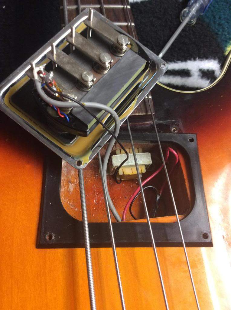
The transformer - I have no idea what it does or if it is for sure a transformer. Anyways, theres an image of this which resided in the pickup pocket

The switch (hopefully drawn correctly) has what I believe was a ground going from it to the Volume pot. Its the floating line next to it.

There is also a lone wire connecting the bottoms of the tone and volume pots. I think this served as the ground for this odd wiring scheme.

Essentially, if anything is obvious to you please bring it up. TIA.
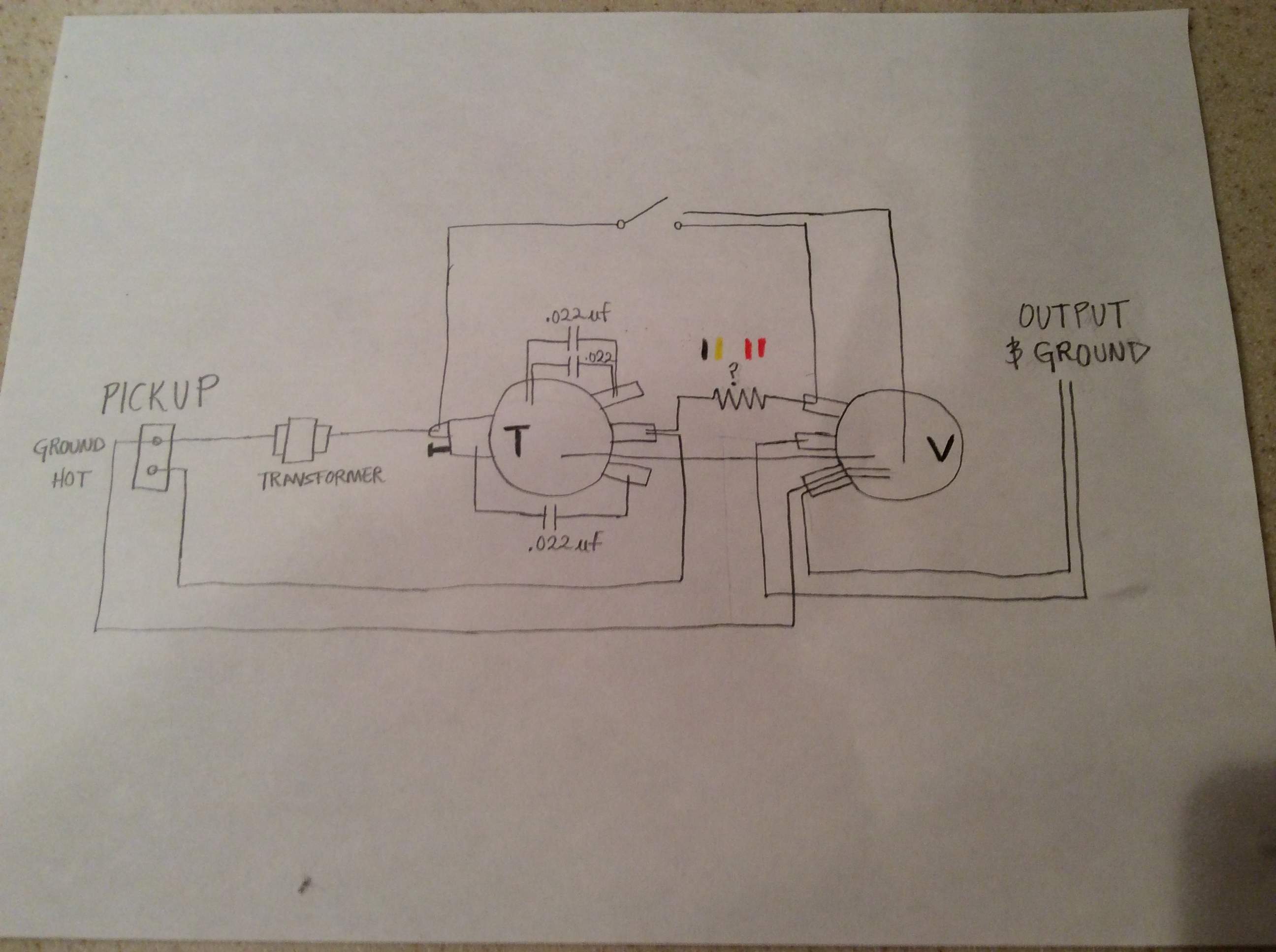
Suck Switch Diagram.JPG

Suck Switch 1.jpg
Transformer and BiSonic.jpg
 
The resistor is 220k. Is the coil (labelled "transformer") in series with the pup ground part of the stock circuit? That's the always on treble suck. Did you try bypassing it? The circuit looks like it might actually work OK that way.

EDIT: I have to say, that coil looks like someone's attempt at passive humbucking. Or something.
 
Last edited:
Heres a link to a thread from when I first got it.
http://www.talkbass.com/threads/nbd-1967-sunburst-starfire-ii.1064769/

The resistor is 220k. Is the coil (labelled "transformer") in series with the pup ground part of the stock circuit? That's the always on treble suck. Did you try bypassing it? The circuit looks like it might actually work OK that way.

EDIT: I have to say, that coil looks like someone's attempt at passive humbucking. Or something.

I'm not sure what you mean okcrum. The first I did when trying to solve this issue was disconnect the coil. All that did was disable the switch but the treble loss was still there. This is the stock circuit as it was connected in 1967 by Guild. I don't think it has anything to do with passive humbucking.
 
Starfire-bass.png

The coil is not for hum cancelling. It's an inductor, part of the tone control circuit - similar to a Tonestyler or the Gibson Vari-tone circuit.

Just for grins, I converted your drawing to a schematic. (Schematics make more sense to me than a pictorial diagram.) Wow, it's a weird circuit. It looks like if the tone control is turned one way, it rolls off the treble like a normal passive tone control. Turned the other way, it looks like it would turn down mids - a passive mid scoop? Engaging the switch would suck out the bass, as you stated in your first post. Of course there's always a chance my schematic is completely wrong.

The doubled-up 0.022 capacitors was probably just an economizing move so they don't have two types of caps. The two caps wired in parallel forms a 0.044 cap, pretty close to the standard 0.047 cap that's commonly used on Fender tone controls.

I would at least try bypassing the weird tone control and seeing how the pickup sounds going straight to the amp. Back when this bass was made, people's expectation of what a bass was supposed to sound like were different than today. Maybe they were trying to make it sound more like an acoustic upright by making a midrange heavy tone circuit.
 
  • Like
Reactions: wisconsindead
Thanks Crater! I was hoping to create a diagram like yours, but too many uncertainties drove me to just use a picture. Appreciate it.

The function of the switch is to drop the bass frequencies, as you said to give a more upright bass tone. Mostly a gimmick thing.

A few months ago I took it all apart and wired normally (Gibson Les Paul). Then, because I don't use tone pots or the bridge pup, I now it wired from neck straight to the ouput. Most of whats on the bass is for looks lol. It sounds great this way, though I should probably add a volume pot for when I need it quickly.

The issue was that somehow even when the switch wasn't engaged that it sucked treble from the neck pickup. How did it do this!?
 
The circuit rolls off the top end no matter where the switch is connected, the more so because it's working into the 220k resistor in series with the volume pot. All you can adjust is how low it starts rolling off. If you represent the tone pot with two resistors it might be more apparent. Turned one way, the tone pot just rolls off all the highs. Turned the other way, it makes a midrange scoop in the response while also filtering the high end. Choose your mud.
 
Last edited:
No the series resistor doesn't have much to do the lack of treble. The tone control is basically a pan pot between "treble cut" and what was apparently supposed to be a "mid cut." Although the inductor should present a high impedance to treble signals, it's probably not well implemented. It's more the fault of the single 0.022 cap on the tone pot. Cut that cap off the pot and it would basically be a standard tone control. Then the inductor would be completely out of the circuit unless the switch was turned on.
 
No the series resistor doesn't have much to do the lack of treble. The tone control is basically a pan pot between "treble cut" and what was apparently supposed to be a "mid cut." Although the inductor should present a high impedance to treble signals, it's probably not well implemented. It's more the fault of the single 0.022 cap on the tone pot. Cut that cap off the pot and it would basically be a standard tone control. Then the inductor would be completely out of the circuit unless the switch was turned on.

The series resistor forms an LR high pass filter when the switch is closed, more or less, plus it will change the Q ("sharpness") of the mid scoop. It's probably selected as a compromise. Not knowing the pot values we have to guess how much tonal effect it has in either switch position. Cutting the single cap and leaving the switch off is the way to go.
 
Last edited:
So the single 0.022 cap connected to the pot and its little attachment was somehow always on or in phase or?

Basically yes. The tone pot controls how "attached" it is to the circuit, and therefore how much signal is removed. Here's a simplified schematic where it's easier to see what's going on electronically. Do you know what the values are of the pots? If the tone pot is 500K or 1 meg, it might be the 'flat' tone is in the center at '5' and not rolled up to '10' like most passive tone controls.
Starfire-bassV2.png