This continues from part 1 http://www.talkbass.com/forum/showthread.php?t=502922
There are several ways to make the transition for the fibers from fingerboard to neck. This way will work for all type neck joints.
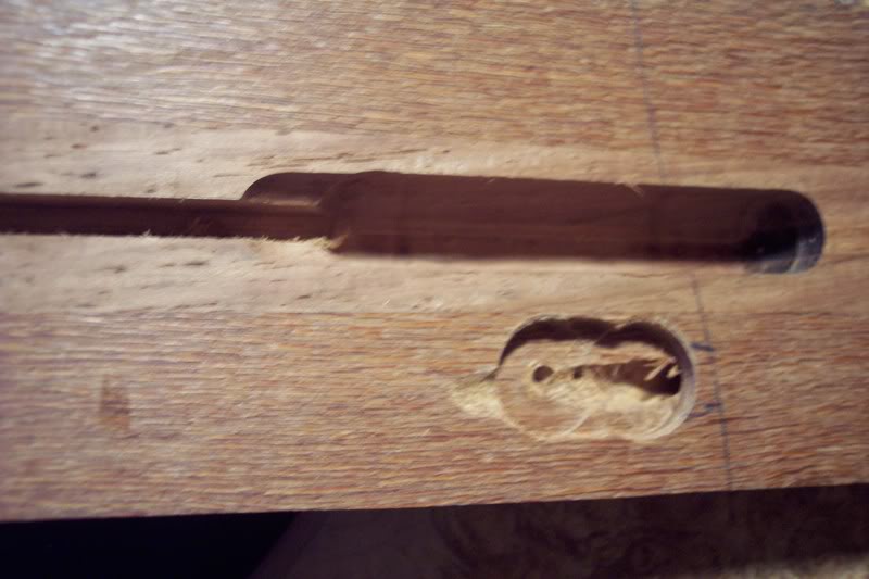
I route a small "landing" for the fibers to enter the neck, I used a fostner bit to do this. I then drill a hole at an angle from the "landing" to the end of the neck, the hole exits at the bottom of the neck. In this photo you can see the truss rod channel, and the landing right under it, you can also see the angled hole at the right in the landing. The blue line is where I’ve marked out the end of the fingerboard.
The fingerboard then gets glued on at this point. The gluing process is the same as normal only that extra care should be taken that the fibers are seated well and do not obstruct the glue joint. I usually dry fit the board several times to make sure all is well. Check to make sure all is flush, adjust the landing if needed.
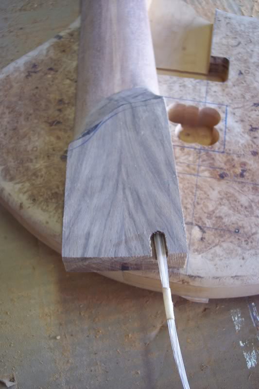
With the fingerboard glued on I then move on to gluing on the neck tranny, I route a small channel on the backside of the transition so the fibers come out of the neck like so. You could also just simply drill with the tranny already glued in place. I did it this way so that I have plenty of wiggle room for the fibers.
The neck pocket is routed and the neck is fitted.
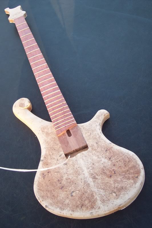
I routed the pickup cavity before setting the neck. Special care was taken to make sure the end of the neck would line up with the pickup route. I did it this way to avoid having to route over the top of the fibers. How bad would it suck to cut one of those at this point? Once the pup cavity is routed, I route a channel to run the fibers to the control cavity.
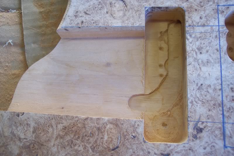
Here you can see where the fibers come out of the neck and run into the pup cavity and then into the control cavity. This will be covered once the cavity is shielded.
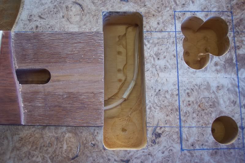
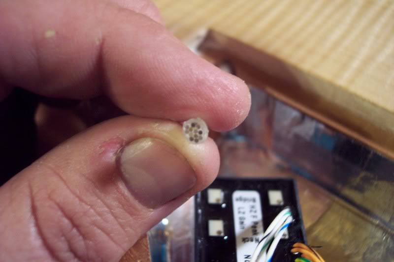
Here are the fibers in the control cavity. I have used a piece of clear shrink tubing to keep them together and help protect them. You must be very careful when using heat near the fibers the heat can easily bend or possibly break them. Use just enough heat to shrink the tubing and no more. As you can see in this photo the fibers are all different lengths, if you applied a light source to them in this condition the dots would not put out the same amount of light, some would be brighter/dimmer than others. Not very attractive!
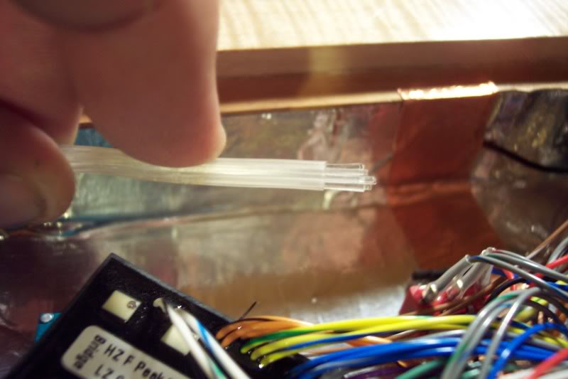
So at this point the best thing to do is to trim the fibers the same length. It’s also a good idea to polish the ends of the fibers so that they are able to transfer the most amount of light possible. I use my Dremel and assorted stones to both trim and polish.
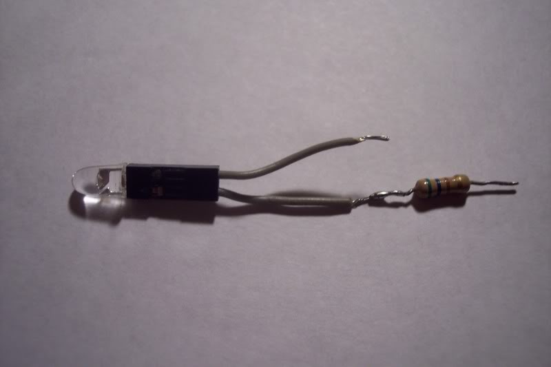
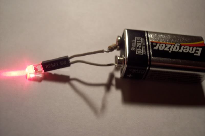
Here's the circuit that will make the magic happen, it really don't get much easier then this! I use a small socket to hold the LED bulb. I've got a bunch of these from old PCs and electronics. They usually hang out on the motherboards and run to switches and what not. You can buy them at Radio Shack too. Depending on the voltage used the LED may need a resistor to keep it healthy. I'm using 9volts and with this particular LED I ended up using a 330 ohm resistor. I like to put the resistor on the negative side of the supply voltage. Here's a simple resistor calculator to help you figure out what resistor you may need. Link Removed
Here is how I couple the light to the fibers. I put a short piece of shrink tubing on the end of the LED I use the same size tubing that I used on the fibers in the cavity. This piece does not get shrunk
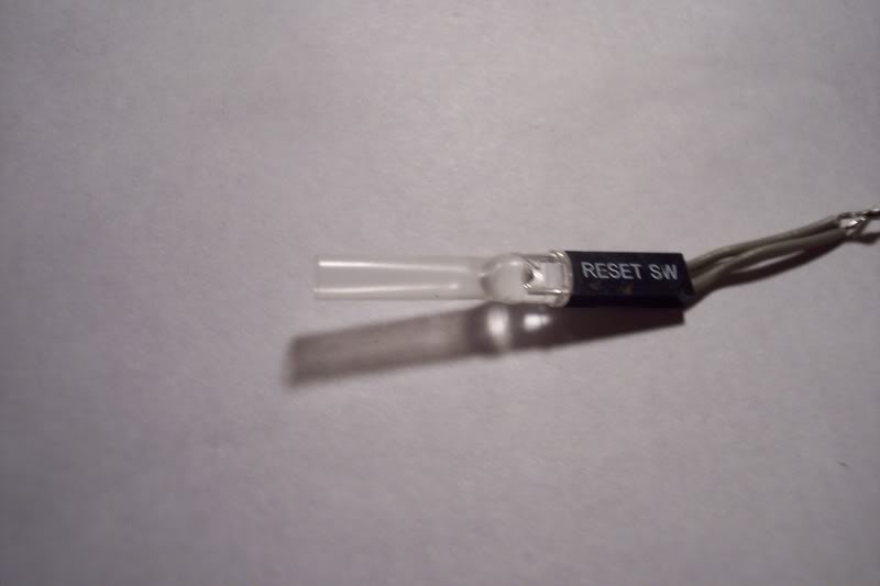
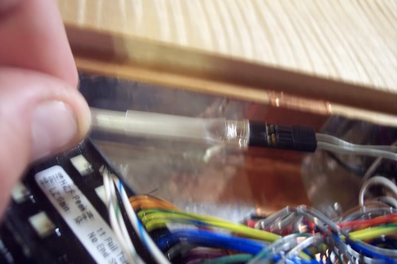
Being that it was not shrunk the tubing fits over the shrunken piece that conduits the fibers. Simply butt the bulb to the end of the fibers, and leave the tubing on the bulb un-shrunk. (blurry photo:scowl
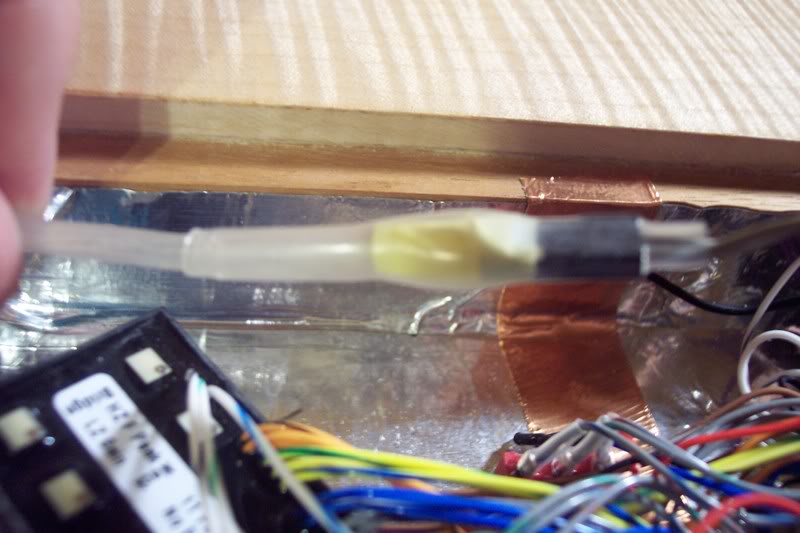
The yellow you see in this photo is nylon electrical tape. I like to wrap the bulb and socket with a small piece of tape to help ensure it will stay put. Now the entire assembly gets an outer sleeve of shrink tubing. Once again be careful while heating, try to keep the heat at a minimum in the bulb area. You don’t want to shrink too much in this area because it’s possible that the tubing could actually shrink to a point to where it gets between the bulb and fibers.
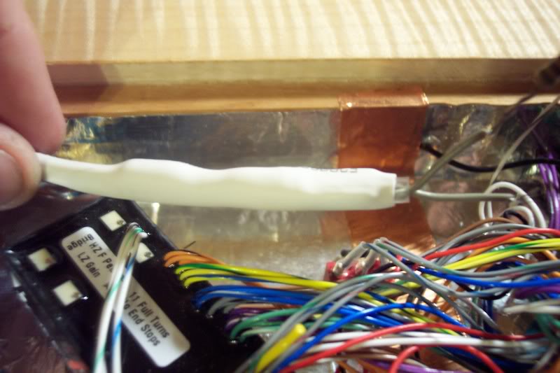
I then use a piece of solid colored tubing and cover the fibers, circuit and all, this will enclose the entire setup only leaving the wire leads exposed.
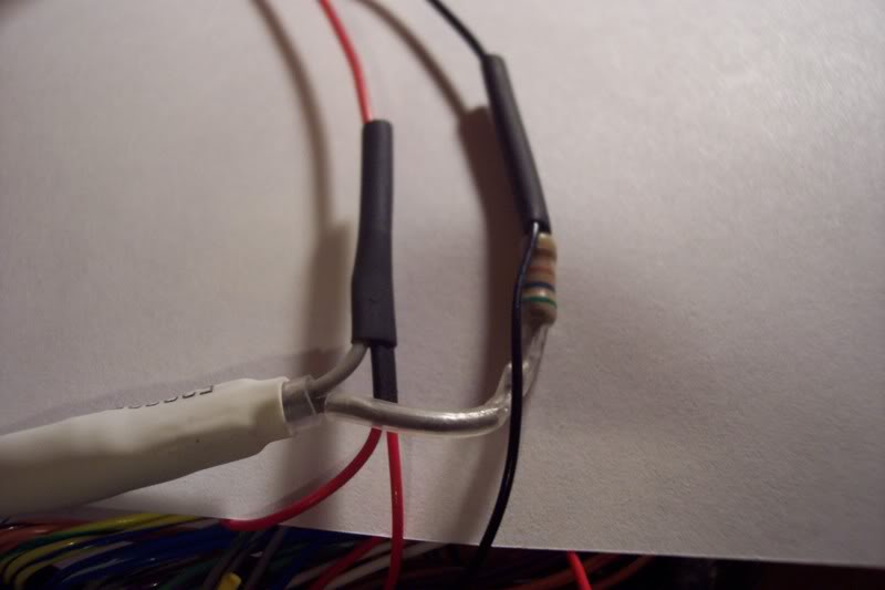
Now wire the bad boy up. The positive lead goes to your battery +, the negative lead goes to the ground/stereo lug on the output jack, this is usually the same one that your preamp goes to, this will cut the light on whenever a plug is inserted in the jack and turn off when the plug is removed. If you don't have a jack like this you may want to use a small switch.
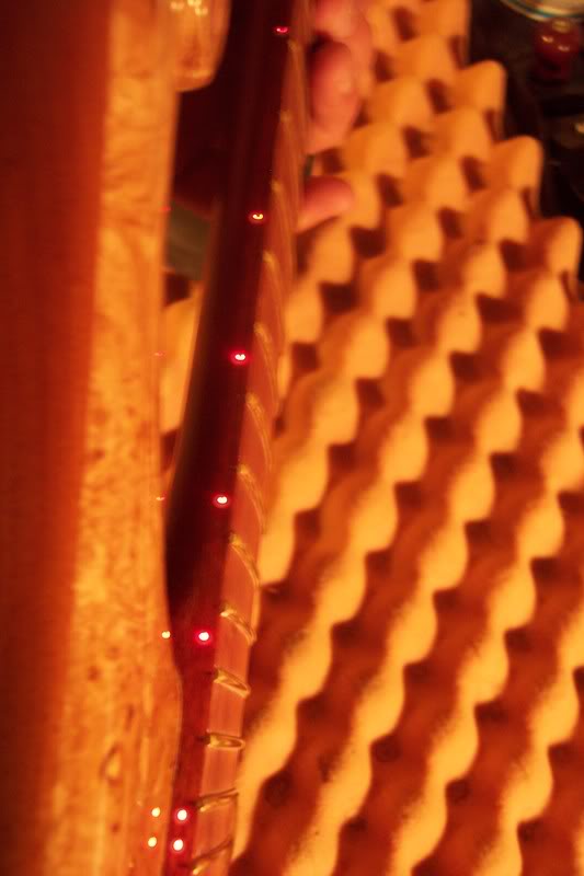
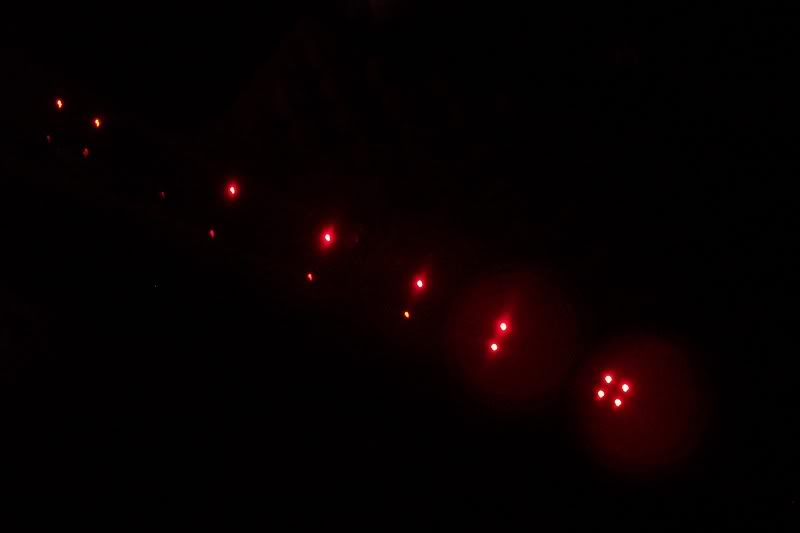
That’s pretty much it, I’m sure I’ve left something out here and there if something is unclear please feel free to PM me. Here are the fibers in action, I'll take better pictures later when this bass is completed.
There are several ways to make the transition for the fibers from fingerboard to neck. This way will work for all type neck joints.
I route a small "landing" for the fibers to enter the neck, I used a fostner bit to do this. I then drill a hole at an angle from the "landing" to the end of the neck, the hole exits at the bottom of the neck. In this photo you can see the truss rod channel, and the landing right under it, you can also see the angled hole at the right in the landing. The blue line is where I’ve marked out the end of the fingerboard.
The fingerboard then gets glued on at this point. The gluing process is the same as normal only that extra care should be taken that the fibers are seated well and do not obstruct the glue joint. I usually dry fit the board several times to make sure all is well. Check to make sure all is flush, adjust the landing if needed.
With the fingerboard glued on I then move on to gluing on the neck tranny, I route a small channel on the backside of the transition so the fibers come out of the neck like so. You could also just simply drill with the tranny already glued in place. I did it this way so that I have plenty of wiggle room for the fibers.
The neck pocket is routed and the neck is fitted.
I routed the pickup cavity before setting the neck. Special care was taken to make sure the end of the neck would line up with the pickup route. I did it this way to avoid having to route over the top of the fibers. How bad would it suck to cut one of those at this point? Once the pup cavity is routed, I route a channel to run the fibers to the control cavity.
Here you can see where the fibers come out of the neck and run into the pup cavity and then into the control cavity. This will be covered once the cavity is shielded.
Here are the fibers in the control cavity. I have used a piece of clear shrink tubing to keep them together and help protect them. You must be very careful when using heat near the fibers the heat can easily bend or possibly break them. Use just enough heat to shrink the tubing and no more. As you can see in this photo the fibers are all different lengths, if you applied a light source to them in this condition the dots would not put out the same amount of light, some would be brighter/dimmer than others. Not very attractive!
So at this point the best thing to do is to trim the fibers the same length. It’s also a good idea to polish the ends of the fibers so that they are able to transfer the most amount of light possible. I use my Dremel and assorted stones to both trim and polish.
Here's the circuit that will make the magic happen, it really don't get much easier then this! I use a small socket to hold the LED bulb. I've got a bunch of these from old PCs and electronics. They usually hang out on the motherboards and run to switches and what not. You can buy them at Radio Shack too. Depending on the voltage used the LED may need a resistor to keep it healthy. I'm using 9volts and with this particular LED I ended up using a 330 ohm resistor. I like to put the resistor on the negative side of the supply voltage. Here's a simple resistor calculator to help you figure out what resistor you may need. Link Removed
Here is how I couple the light to the fibers. I put a short piece of shrink tubing on the end of the LED I use the same size tubing that I used on the fibers in the cavity. This piece does not get shrunk
Being that it was not shrunk the tubing fits over the shrunken piece that conduits the fibers. Simply butt the bulb to the end of the fibers, and leave the tubing on the bulb un-shrunk. (blurry photo:scowl
The yellow you see in this photo is nylon electrical tape. I like to wrap the bulb and socket with a small piece of tape to help ensure it will stay put. Now the entire assembly gets an outer sleeve of shrink tubing. Once again be careful while heating, try to keep the heat at a minimum in the bulb area. You don’t want to shrink too much in this area because it’s possible that the tubing could actually shrink to a point to where it gets between the bulb and fibers.
I then use a piece of solid colored tubing and cover the fibers, circuit and all, this will enclose the entire setup only leaving the wire leads exposed.
Now wire the bad boy up. The positive lead goes to your battery +, the negative lead goes to the ground/stereo lug on the output jack, this is usually the same one that your preamp goes to, this will cut the light on whenever a plug is inserted in the jack and turn off when the plug is removed. If you don't have a jack like this you may want to use a small switch.
That’s pretty much it, I’m sure I’ve left something out here and there if something is unclear please feel free to PM me. Here are the fibers in action, I'll take better pictures later when this bass is completed.