The Jack Plate on my Ampeg SVT-810E Classic is damaged beyond repair (part # 16-764-02). I bought a new one online, but it is for the Heritage Cabinet (part # 16-764-03). Unfortunately the two are not the same. The Classic jack plate has four wires coming out of it and the Heritage has eight. The Classic jack plate is not in stock anywhere so I'd like to use the Heritage with my Classic cabinet. Of the 8 wires coming from the Heritage plate, two pair are labeled "upper" and the other two pair "lower," and each wire IS labeled + or -. So I'm wondering if I can just run each pair of wires to two speakers that would be joined in parallel? There is no wiring diagram available on line for the Heritage like there is on the Classic. Perhaps someone here knows how one would wire the Heritage plate in a Classic cabinet?

Enjoy the benefits of a premium membership!
Upgrade Account
-
TalkBass has been independent since 1998. Add your voice.
Create a free account to reply to discussions, view embedded media, and browse with fewer display ads.
Join free Log in
Want zero display ads or expanded classifieds tools? Compare plans.
You are using an out of date browser. It may not display this or other websites correctly.
You should upgrade or use an alternative browser.
You should upgrade or use an alternative browser.
Jack Plate for Ampeg SVT-810E Classic
- Thread starter AmpegDave
- Start date
More options
Who Replied?
- Feb 12, 2006
- 60,978
- 5
- 220,735
- Disclosures
- Development Engineer-Mesa Boogie, Development Engineer-Genzler (pedals), Product Support-Genz Benz
- Feb 12, 2006
- 60,978
- 5
- 220,735
- Disclosures
- Development Engineer-Mesa Boogie, Development Engineer-Genzler (pedals), Product Support-Genz Benz

Check your cab's original wiring to see if it matches this:

The colors of the wires may not match the diagram.
Also check to make sure the drivers are 32 ohms.
This wiring scheme breaks down into two parallel circuits, upper and lower. Each circuit consists of four 32-ohm drivers in parallel. This gives you 8 ohms per circuit. Two 8-ohm circuits in parallel gives you 4 ohms.
If you are not clear, parallel means all of the + are tied together and all of the - are tied together.
In order to make the Heritage jack plate work, it first has to fit the cutout in the cab. If it does, then you will need to fabricate some jumpers because it appears to only have wires for four drivers.
Given the way the cab is made, you probably run one pair of wires to each of the four chambers; something like this:
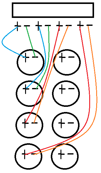
I don't know the color code, but the jack panel appears to be labeled clearly.
You also need to run jumpers across the speakers in each chamber:
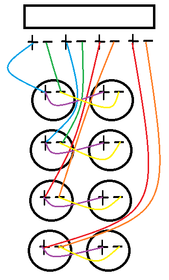
+ to + and - to -
Let me be clear....this is my guess as to how the cab should be wired. It's up to you to confirm this is correct and gives you the proper impedance.
If the old wiring harness is in good repair, you can probably use it to form your jumpers. Make sure you confirm everything before you start cutting.
These are the current standard OEM drivers for the 810E
Link Removed
I posted this so you can see the - and + on the terminals. Also - has two spade connectors and + has two spade connectors.
After you get everything wired up, do the 9V battery test to confirm all drivers are wired in phase.
The colors of the wires may not match the diagram.
Also check to make sure the drivers are 32 ohms.
This wiring scheme breaks down into two parallel circuits, upper and lower. Each circuit consists of four 32-ohm drivers in parallel. This gives you 8 ohms per circuit. Two 8-ohm circuits in parallel gives you 4 ohms.
If you are not clear, parallel means all of the + are tied together and all of the - are tied together.
In order to make the Heritage jack plate work, it first has to fit the cutout in the cab. If it does, then you will need to fabricate some jumpers because it appears to only have wires for four drivers.
Given the way the cab is made, you probably run one pair of wires to each of the four chambers; something like this:
I don't know the color code, but the jack panel appears to be labeled clearly.
You also need to run jumpers across the speakers in each chamber:
+ to + and - to -
Let me be clear....this is my guess as to how the cab should be wired. It's up to you to confirm this is correct and gives you the proper impedance.
If the old wiring harness is in good repair, you can probably use it to form your jumpers. Make sure you confirm everything before you start cutting.
These are the current standard OEM drivers for the 810E
Link Removed
I posted this so you can see the - and + on the terminals. Also - has two spade connectors and + has two spade connectors.
After you get everything wired up, do the 9V battery test to confirm all drivers are wired in phase.


Is your current/original jack plate for one of the splitting cabs? They went to that jack plate around 2001 if I recall.
They do not appear to be the same design as the heritage despite the similar/identical function
standard 16-764-02
Invalid Link Removed
Heritage 16-764-03
Invalid Link Removed
the heritage one appears to be fairly clearly labeled for top and bottom speakers, maybe rewire the cab following the instructions above if you cannot get the correct replacement part.
They do not appear to be the same design as the heritage despite the similar/identical function
standard 16-764-02
Invalid Link Removed
Heritage 16-764-03
Invalid Link Removed
the heritage one appears to be fairly clearly labeled for top and bottom speakers, maybe rewire the cab following the instructions above if you cannot get the correct replacement part.
The actual internal cable I used actually includes parallel jumps from the first to second row and also from the third to fourth row. Rather than cut these out and ruin the cable that I may need for future use, redundantly connected it in full (see figure below), even though separate power is coming to the second and fourth rows. As all is in parallel, hopefully this will not create a problem.
Last edited:
The actual internal cable I used actually includes parallel jumps from the first to second row and also from the third to fourth row. Rather than cut these out and ruin the cable that I may need for future use, redundantly connected it in full (see figure below), even though separate power is coming to the second and fourth rows. As all is in parallel, hopefully this will not create a problem.
As long as you get the polarity correct on all connections, it should be fine. If one of the connections is reversed, it causes a short.
I have all Positive to Positive in parallel exactly as shown in the diagram. We will see next week when I turn the amp on. I had to travel some to get this amp, and I'm staying with friends for a week before I can get home to plug a guitar into it. I suppose I could turn it on and see if it smokes, ha!
I had sold this amp to a college kid (son of a friend) over ten years ago. He's moving and it's too big so he offered it back to me for $500 (including amp). Only problem was that he destroyed the jack plate when it tipped over once with a cable plugged in.
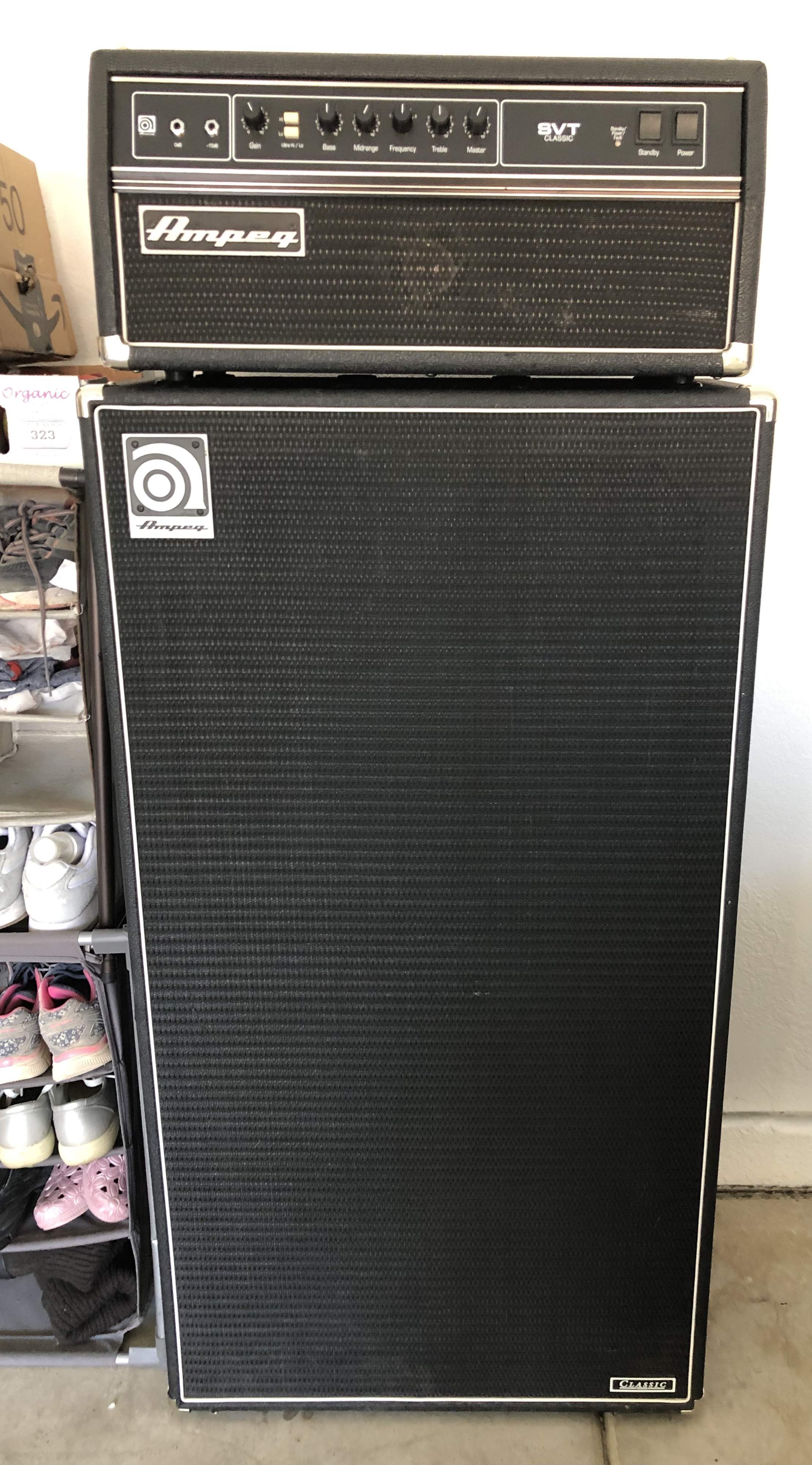
I had sold this amp to a college kid (son of a friend) over ten years ago. He's moving and it's too big so he offered it back to me for $500 (including amp). Only problem was that he destroyed the jack plate when it tipped over once with a cable plugged in.
Last edited:
I have all Positive to Positive in parallel exactly as shown in the diagram. We will see next week when I turn the amp on. I had to travel some to get this amp, and I'm staying with friends for a week before I can get home to plug a guitar into it. I suppose I could turn it on and see if it smokes, ha!
I suggest doing the 9V battery test before connecting the cab to an amp.
How does the 9V battery test work?
Remove the front grill and insert a 1/4" to 1/4" speaker chord into one of the lower 1/4" jacks.

Short the 9V battery's across the tip and ring of the unterminated 1/4" plug on the other end of the speaker chord. This should cause all eight of the drivers to move in the same direction. With modern drivers I believe + terminal of the battery to the tip of the 1/4" plug should cause the drivers to push out of the cab.
The top 1/4" jack is switching and breaks the cab into an upper and lower 410. If you insert the speaker chord into the top jack and perform the 9V test, only the top four drivers should move.
If you have two 1/4" speaker chords, insert one in the top jack and one in the bottom jack. Now if you connect the 9V to the chord plugged into the bottom jack, only the bottom four drivers should move.
I did the 9 volt battery test as Wasnex suggested and it worked exactly as he described (for a proper circuit). Touching the positive lead to the tip of the 1/4" cable made all cones come forward when using one of the lower jacks and using the upper jack caused only the top four to come forward. Mission accomplished.
I was also pleasantly surprised to find that the speakers in this 2003 SLM cabinet are Eminence.
Eminence have been the standard speaker in these since about the mid 70s. Few different versions of the speakers over the years, but eminence are what they should be.


