• TalkBass has been independent since 1998. Add your voice.
    Create a free account to reply to discussions, view embedded media, and browse with fewer display ads.
    Join freeLog in
    Want zero display ads or expanded classifieds tools? Compare plans.

Machine Shop Practice: Making Custom Metal Hardware For Basses

Cool! That's a lifetime tool. I believe that is an older Starrett, like from the 1940's. It's probably already been a lifetime tool several times. You are just the current owner. Treasure it and use it in good spirit!

Correction:

Your square isn't a Starrett, it's a Brown & Sharpe! I happened to be looking around my bench for something, and I discovered that I have one of them, too. Browne & Sharpe is the other classic American precision tool maker. Equal in quality and prestige to Starrett.

Huh, it was listed as a Starrett. Should I make a big deal out of it?

ebaylisting.jpg
 
  • Like
Reactions: MovinTarget
Look real close at it. There should be some fine lettering along the center of the ruler and along the flat edges of the two heads. Small engraving. A Brown & Sharpe will say Brown & Sharpe Mfg Co., Providence RI. A Starrett will say Starrett, Athol, Mass. The old Starretts and Brown & Sharpes are very similar in appearance.

It doesn't really matter which one yours is. Those were the two top American precision measuring tool makers in the US, and they still are. They are equals in quality and reputation.

You got a lifetime tool at a reasonable price.
 
Look real close at it. There should be some fine lettering along the center of the ruler and along the flat edges of the two heads. Small engraving. A Brown & Sharpe will say Brown & Sharpe Mfg Co., Providence RI. A Starrett will say Starrett, Athol, Mass. The old Starretts and Brown & Sharpes are very similar in appearance.

It doesn't really matter which one yours is. Those were the two top American precision measuring tool makers in the US, and they still are. They are equals in quality and reputation.

You got a lifetime tool at a reasonable price.

Thanks Bruce. It doesn't seem to say either - I took a close up of what appears to be LS Starrett, but doesn't spell it out.

SquareCloseup.jpg
 
When my woodworking buddy and I used to discuss expensive machinery purchases he would say "Why don't we just go halfsies on it and keep it at my place?". :)
I've made plans a couple times to join a makerspace that has some of the serious equipment I can't justify buying at home (like a bandsaw, which I might use maybe four times a year, assuming making basses becomes a regular hobby by my standards of regular). It hasn't happened in part because of budgeting and in part because they are missing some things that would make it easier for me to justify the expense. One of the penalties of living in a relatively small city, I guess.
 
When my woodworking buddy and I used to discuss expensive machinery purchases he would say "Why don't we just go halfsies on it and keep it at my place?". :)

Hah! Yeah, that works. You've seen my huge Kondia milling machine. It actually belongs to my friend Thomas. He bought it for $100 from a long time retiring machinist friend. But he had no place to put it. I offered that he could store it for a while down here in the Secret Underground Lab. You know, while he is figuring out where he could fit it. 3400lbs of old Spanish cast iron. After about a year of quiet storage, I started thinking that I could use that machine.....

So, I offered that if he let me move it into my shop, I'd clean it up, wire it up, and make it useful. And he could come over here occasionally and use it. That was about 5 years ago. I've learned to appreciate that knarly old beast, and I use it regularly now. It's really good at milling aluminum. In the last year, I've switched almost all of my milling operations over to the Kondia, and I use the Green Mill/Drill just for precision Machine Drilling.

Thomas does occasionally stop in and borrow some time on the Kondia. I intend to eventually buy it from him.
 
Last edited:
A quick note about the parallels:

One hidden feature of vises made for milling machines is that the bottom surface between the jaws is precision ground to be parallel to the bottom surface of the vise. To tight tolerances, like +/- 0.0005".

Real Machinists doing real precision machine work use parallels that are hardened and ground to within 0.0002". You can buy them in sets. That's what you use if you are machining your parts to 0.001" tolerance or better.

Here's a relatively cheap import set, for example. A top quality set can be a few hundred bucks.

https://www.amazon.com/HHIP-3900-3012-Precision-Parallel-Wooden/dp/B00DVTXSBU/ref=sr_1_11?crid=1HNU56AVQKN60&keywords=parallels+machinist&qid=1685064232&sprefix=parallels,aps,222&sr=8-11&th=1

For bass part work, I get along fine with my home made aluminum bar stock parallels. When I mill blocks with them, I'm usually +/- 0.002" in final thickness
Or use rods made from wedge steel that usually have been ground to h8 tolerance.
It might be overkill for bass bridges but it is a nice and resonable priced option.
 
As an Amazon Associate, TalkBass may receive commissions from qualifying purchases made via links on this site.
  • Like
Reactions: MovinTarget
I've made plans a couple times to join a makerspace that has some of the serious equipment I can't justify buying at home (like a bandsaw, which I might use maybe four times a year, assuming making basses becomes a regular hobby by my standards of regular). It hasn't happened in part because of budgeting and in part because they are missing some things that would make it easier for me to justify the expense. One of the penalties of living in a relatively small city, I guess.
I should elaborate on this since I sounded kinda harsh about it: The local makerspace is a co-op; joining would allow me to request them to get tools, which they can as budget allows (and be more likely to since more members means more money), so it's not a dead end option of "they got it or they don't", and I'm still tempted to join them, though I can't embark on any projects right now anyway so I may as well hold off.
 
Moving on to Machine Drilling, using a milling machine.

The basic principle is the same as Machine Drilling with a drill press. The part is held tightly in a strong vise, usually on parallels and against a stop. The vise is bolted solidly to the milling machine's table. The table can be moved in the X and Y axes to position the part under the drill. Like a bigger version of that X-Y vise on the drill press. On the milling machine, those two axes are measured by DRO's (or micrometer dials). The part can be positioned within 0.001" accuracy, just using the DRO's and your numbers from the part drawing. You don't need to use a Master, but you can if you have one.

Before we get into Machine Drilling, we should go through the basics of "zeroing" a milling machine. You'll hear Real Machinists refer to "Indicating It In". They use that term because, in the high precision world, the process is usually done using Dial Indicators, another type of precision measuring tool. I'm not going to bore you with all that here. If you get yourself a milling machine, you really should read a book on machine shop practice. Here, I'm going to show you some simple shortcuts that I use all the time.
IMG_9034BX.jpg


IMG_9041BX.jpg


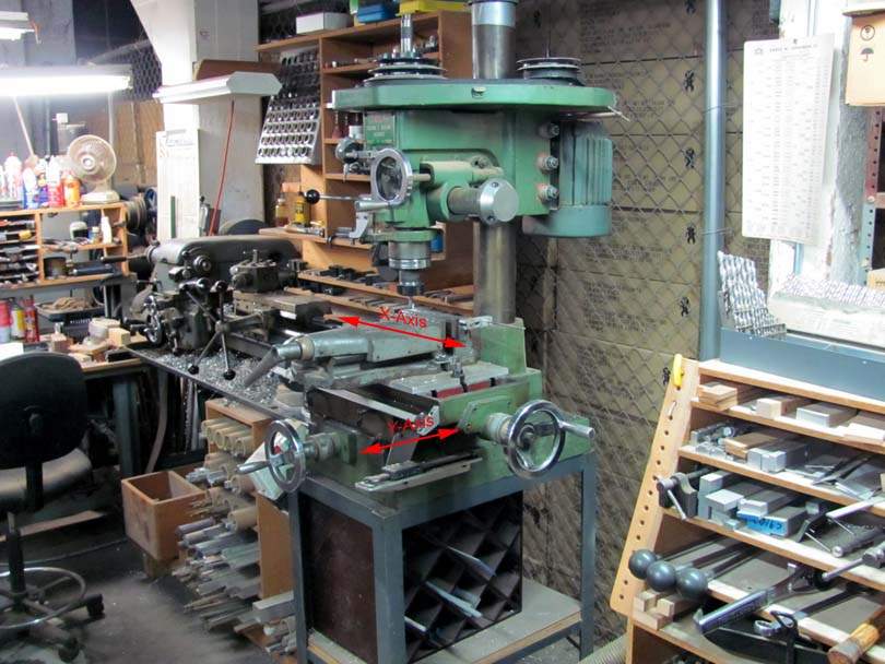
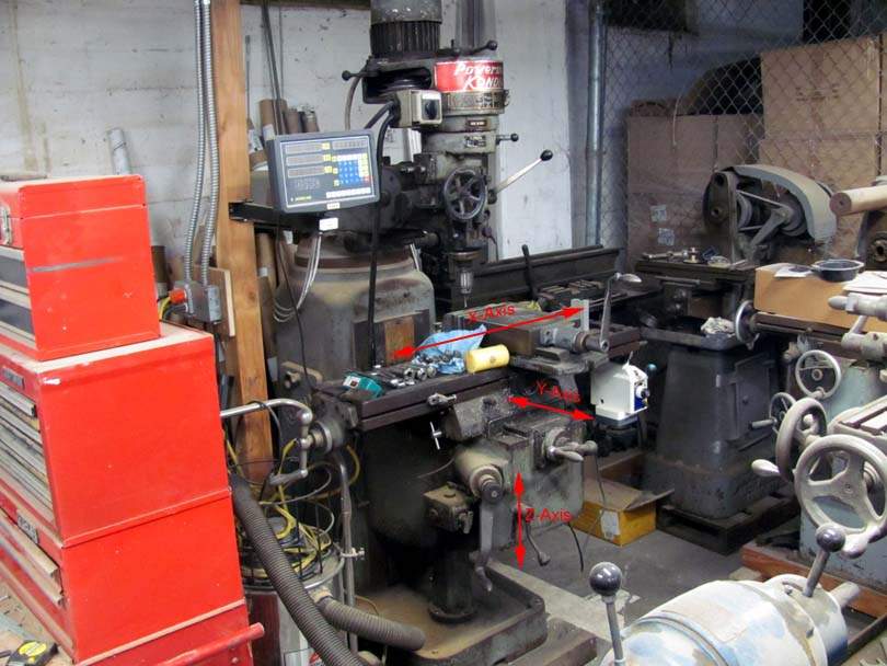
If you haven't picked up on it already, the standard convention for milling machines is that the X-axis is the left-to-right movement of the table. The X-axis has the longest travel; longer distance of movement. On a Mill/Drill, like my green one, the table is about 20" long and the X travel is around 12". On a big turret mill like my Kondia, the table is about 48" long, and the X travel is almost 24". The crank handles on the left and right ends of the table move the X-axis. Most mills have cranks on both sides.

The Y-axis is the forward-backward movement. On the Mill/Drill, the Y travel is 6". On the Kondia, it's 12". The Y-axis is moved by the crank on the front of the machine.

Full size milling machines also have a Z-axis. The whole table assembly is mounted on a Knee, which cranks up and down vertically. The Kondia has a Z travel of about 12". That's the big crank handle on the front, angled to the left. It's a low gear ratio, because it's lifting about 1000 lbs.

Mill/Drill machines don't have that whole knee and huge cast iron base under the table. That's why they are so much smaller, lighter weight and less expensive. On a Mill/Drill, you adjust the Z-axis by moving the quill up and down.

When Machine Drilling in a milling machine, you are mostly using the X and Y axes for the precision location of the hole. The Z-axis is the quill, and does the drilling like a drill press.

Zeroing a milling machine:

To set up a milling machine for Machine Drilling, you first have to first establish where the "0,0" point is. That's the point from which all the measurements are taken. Where you establish 0,0 will depend on how you did your drawings for the part.

When I draw up parts in AutoCad, I use Ordinate Dimensioning for most things. It makes things easier to read, with fewer mistakes. In Ordinate Dimensioning, you establish a 0,0 point on the drawing, and all of the dimension numbers are in relation to that single point. In the example of an aluminum block that has a pattern of holes drilled in it, in the plan view, I usually establish 0,0 as the upper right corner of the block. Then all the hole locations are dimensioned, in X and Y distances, from that corner.

On the milling machine, I do the same thing. I set 0,0 as the right rear corner of the block, as it is clamped in the vise. The vise is bolted down to the mill's table so the back stationary jaw is parallel to the Y-axis. The vise is "Indicated In" so that is truly parallel to the Y-axis within 0.001". I won't show that process here, but we can go over it later if any of you are interested. For now, assume that the vise's rear jaw is accurately parallel to the Y-axis.

So, the back fixed jaw of the vise will become the Y=0 line. In the vise, the block will seat solidly against that jaw. The X direction is controlled by the Stop, which I normally have set up on the right side. With the block in there in that position, I want to set the DRO's to read 0,0 when the spindle is directly over the right rear corner of the block.

The way to do that is called Finding The Edge. It's a classic machine shop technique. There are different tools and methods, but the idea is to find out when the exact centerline of the spindle is just crossing over the edge of something. To locate the spindle over the right rear corner of the block, first I locate the edge of the back jaw of the vise, zero the Y-axis DRO, then locate the right side edge of the block, as it sits against the stop. And zero the X-axis DRO. That makes the two DRO's read 0,0 over the right rear corner of the block.

For reference, here are two of the classic tools that Real Machinists use to Find Edges to high accuracy:

IMG_9628B.jpg


The tool on the right is called a Wiggler, fitted with an edge-finding tip. Very old-school. Wigglers go back more than 100 years. When it finds an edge, it stops wiggling! On the left is an Electronic Edge Finder, circa mid-'90's. It has an LED lamp and a battery inside. It lights up when it finds an edge! Somewhere around here I have a classic mechanical Edge Finder, but I couldn't find it at the moment. But I'm not going to show you how to use these tools.....Some other time.

Here, I'm going to show you my own quick and easy edge-finding technique, the Pin & Flashlight Method. I kinda figured it out myself, but I'm sure I'm not the first to do it. It's very simple and surprisingly accurate. Like, within 0.001" usually.

All that's needed is a precision steel dowel pin and a small flashlight. I have a 1/4" dia x 2" long dowel pin that I keep right here with my milling machines. It measures exactly 0.2501" diameter. I checked it with a micrometer. I use it in just about every setup. And a small penlight flashlight.

IMG_9621B.jpg


Here's how it works. I'm going to find the edge of the rear vise jaw. I put the dowel pin in the chuck in the spindle, and bring the spindle down so that it overlaps the vise jaw by maybe 1/4" vertically. Then I advance the Y-axis to move the pin close to the jaw....

IMG_9622B.jpg


Real close, almost touching, but not quite.....

IMG_9624B.jpg


Here's the trick: I put the penlight back behind the pin and sight down the line of the jaw from the other side. That little white line of light between the pin and the jaw is the gap. The back light shows it and exaggerates it. Now, I turn the Y-axis crank very gently, a thousandth at a time, and watch that white line get narrower. When the line just clicks off, stop right there! That's when the pin has just touched the surface of the jaw. This is when machine shop work gets exciting! I've Found The Edge!

IMG_9625B.jpg


I reach down and push the ON button of the Y-axis DRO, which resets it to 0.000. Now, the pin is 0.250" diameter. So the spindle centerline is actually 0.125" offset from the edge....I raise the spindle up enough that the pin clears the jaw.....

IMG_9626B.jpg


...And turn the Y-axis crank until the DRO reads 0.125". This puts the centerline of the spindle directly over the edge of the jaw......

IMG_9625B.jpg


....And push the button again, which resets the DRO to 0.000. And that's it! The Edge has been found and the DRO is zeroed to it. I told you this was going to be exciting.

IMG_9627B.jpg


Then, I do the same thing on the X-axis, with the Pin & the Flashlight. I clamp the block in the vise, against the Stop on the right. Bring the pin up against it, find the edge using the flashlight. Zero the X-axis DRO, move it over 0.125", re-zero it.

That's it. The Mill/Drill is now all set to do accurate Machine Drilling, positioning the holes using the numbers on the DRO's. All in relation to the right rear corner of the block.

That's what I'll do next, on those DeTemple bridge blocks....
 
Is there a reason for using a dowel pin that's 0.0001" oversize?

Hah, you picked that up. You are paying attention. Standard steel dowel pins are precision ground to be exactly....0.0001" oversize. A Standard Size Steel 1/4" Dowel Pin is 0.2501" diameter, by specification. The reason is that it is intended to be pressed into a hole in a steel plate, which has been reamed to 0.2500". One ten-thousandth, 0.0001", is the normal interference fit for pressing steel pins into steel plates. They are very accurately ground. If you buy a box of them, and check them all with a vernier micrometer, they will all be 0.2501".

Likewise, an 1/8" Standard Dowel Pin will be 0.1251".
 
Hah, you picked that up. You are paying attention. Standard steel dowel pins are precision ground to be exactly....0.0001" oversize. A Standard Size Steel 1/4" Dowel Pin is 0.2501" diameter, by specification. The reason is that it is intended to be pressed into a hole in a steel plate, which has been reamed to 0.2500". One ten-thousandth, 0.0001", is the normal interference fit for pressing steel pins into steel plates. They are very accurately ground. If you buy a box of them, and check them all with a vernier micrometer, they will all be 0.2501".

Likewise, an 1/8" Standard Dowel Pin will be 0.1251".

I just figured it was to save us OCD folk from having to go another digit of precision to find the absolute center of the pin! :D
 
  • Like
Reactions: BeeTL