
Enjoy the benefits of a premium membership!
Upgrade Account
-
TalkBass has been independent since 1998. Add your voice.
Create a free account to reply to discussions, view embedded media, and browse with fewer display ads.
Join free Log in
Want zero display ads or expanded classifieds tools? Compare plans.
You are using an out of date browser. It may not display this or other websites correctly.
You should upgrade or use an alternative browser.
You should upgrade or use an alternative browser.
Manual for Trace Elliott GP12XV?
- Thread starter TobiasD
- Start date
-
- Tags
- manual trace trace elliott
More options
Who Replied?
If you find it please post on the Team Trace Elliot thread. Looks to be the forerunner of the SMX preamp, everything but the compressors and EQ blend balance thingy.
Hi, did anybody find something?
User manual and/or service manual/schematics would be highly appreciated
User manual and/or service manual/schematics would be highly appreciated

Hi, did anybody find something?
User manual and/or service manual/schematics would be highly appreciated
I found some related stuff. Some of it may be helpful.
My timeline guesstimate: NAD: Trace Elliot VA 350 "all" tube head
Someone else's comments: Franken P: Trace Elliot GP12XV Silverface 1990 Preamp
Not sure if the GP12XV is closer to the GP12X or Hexa preamp. They look significantly different to me.
The GP12 Preamp in the Valve series service docs appears to be the same as in the VA400 service manual. So maybe it's not the right schematic for the Valve series.
Let me know if you want the various docs I have on the VA350 and V400.
Attachments



Thanks for the documents
So it's basically a classic gp12 series 6 with an additional valve somewhere in the circuit. I guess there will not be a schematic for the complete circuit, but we have all the parts of the puzzle.
I just bought the preamp second hand and was advertised as "untested". It should arrive in the next few days, then I'll be able to compare the existing schematics with the actual circuit. With a bit of luck I won't even have to open it (apart out of curiosity). I'll keep you posted.
BTW the GP12x schematic seems to be an smx (which came just after the series 6).
I found the series 6 pre-amp (as part of the AH300 head) here: Invalid Link Removed
So it's basically a classic gp12 series 6 with an additional valve somewhere in the circuit. I guess there will not be a schematic for the complete circuit, but we have all the parts of the puzzle.
I just bought the preamp second hand and was advertised as "untested". It should arrive in the next few days, then I'll be able to compare the existing schematics with the actual circuit. With a bit of luck I won't even have to open it (apart out of curiosity). I'll keep you posted.
BTW the GP12x schematic seems to be an smx (which came just after the series 6).
I found the series 6 pre-amp (as part of the AH300 head) here: Invalid Link Removed
I haven't found any images of preamps labeled GP12X.
Here is a link with gut shots for a GP12XV. GS Fanatic, where music creation begins
I only see one tube.
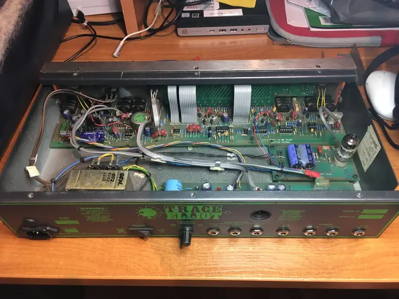
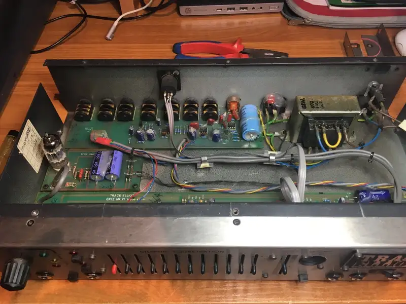
Circuit board is labeled GP12 Mk VI. See left quadrant of second image, just above the fader with a red cap.
Per the Service Manuals for the full amps, the 1st stage of the tube drives the Graphic EQ. The signal is returned to the 2nd tube stage.
Gutshot of a Hexa for comparison. Ref: TRACE ELLIOT HexaValve very rare amazing amp - Amps and Cabs For Sale - Basschat
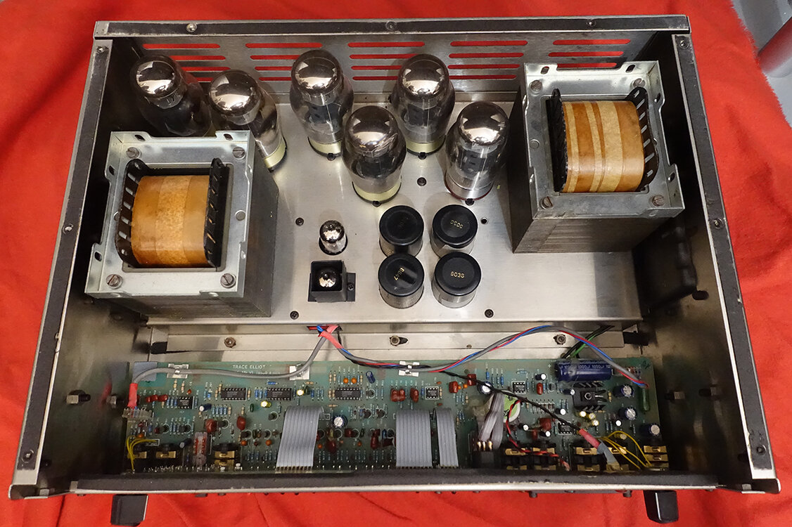

I believe the small signal tube in the black square shield serves the same purpose as the tube in the GP12XV.
Preamp in second Hexa shot looks very similar to Preamp in first GP12XV shot.
So I am starting to think maybe the preamp schematic in the Valve series service manuals is legit and maybe the GP12X is a red herring.
I believe the GP12X schematic shows the EQ is driven by and returns through solid state circuitry. The tube comes later, and from what I see you can adjust the controls to fade the tube in or out of the signal path.
Clear as mud...sorry, I tried.
Here is a link with gut shots for a GP12XV. GS Fanatic, where music creation begins
I only see one tube.
Circuit board is labeled GP12 Mk VI. See left quadrant of second image, just above the fader with a red cap.
Per the Service Manuals for the full amps, the 1st stage of the tube drives the Graphic EQ. The signal is returned to the 2nd tube stage.
Gutshot of a Hexa for comparison. Ref: TRACE ELLIOT HexaValve very rare amazing amp - Amps and Cabs For Sale - Basschat
I believe the small signal tube in the black square shield serves the same purpose as the tube in the GP12XV.
Preamp in second Hexa shot looks very similar to Preamp in first GP12XV shot.
So I am starting to think maybe the preamp schematic in the Valve series service manuals is legit and maybe the GP12X is a red herring.
I believe the GP12X schematic shows the EQ is driven by and returns through solid state circuitry. The tube comes later, and from what I see you can adjust the controls to fade the tube in or out of the signal path.
Clear as mud...sorry, I tried.
It has just arrived, I didn't test all inputs/outputs yet but it works well so far.
So I just opened it for a few pictures and to find one plastic washer from a jack connector that was rattling in the case.
Here is an overview, it has three boards, the classic GP12 preamp, the valve add-on and the rear connections circuit:
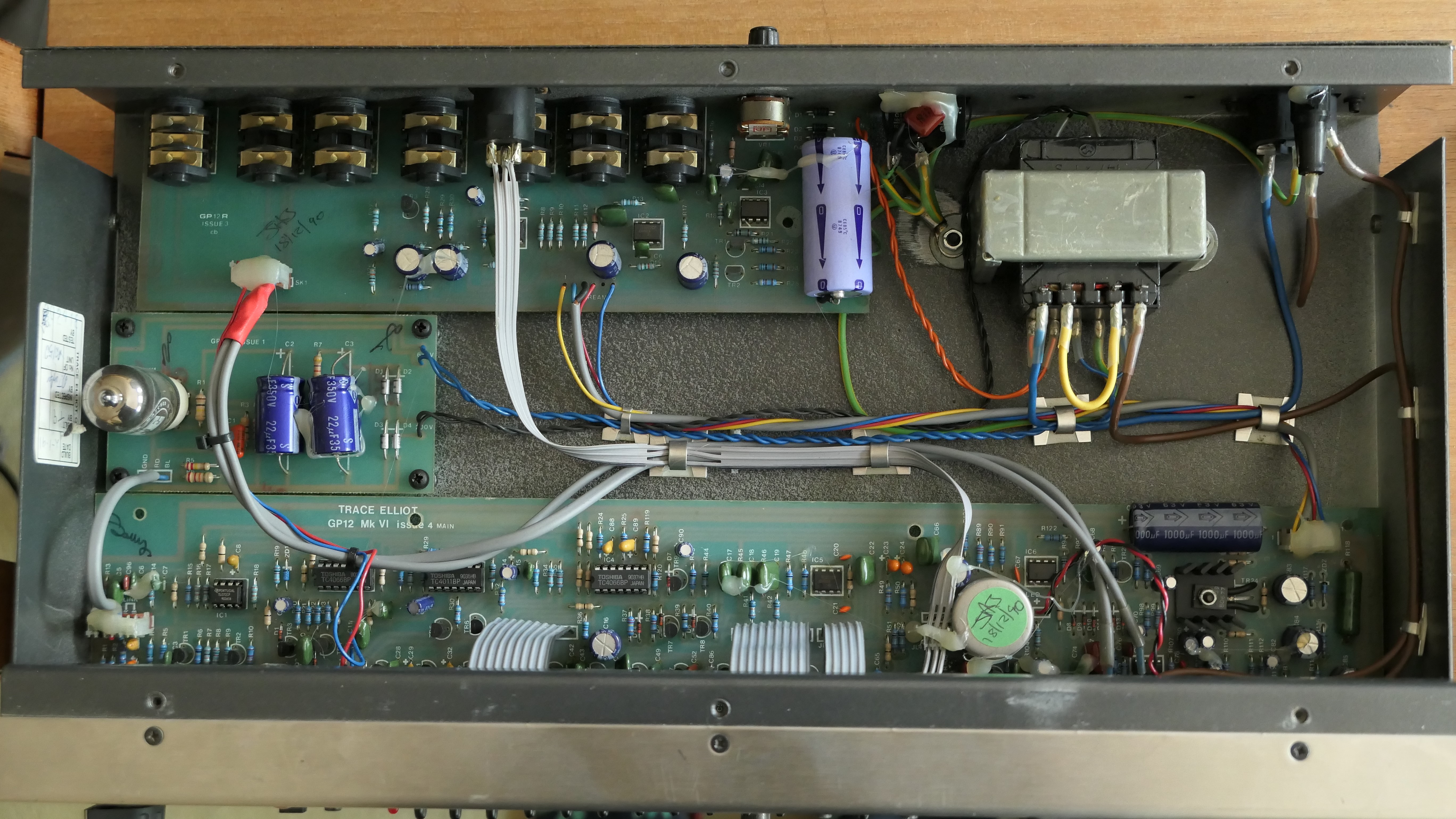


So it looks like the input valve is just an add-on that connects to the otherwise standard GP12 preamp through the "link" connector:
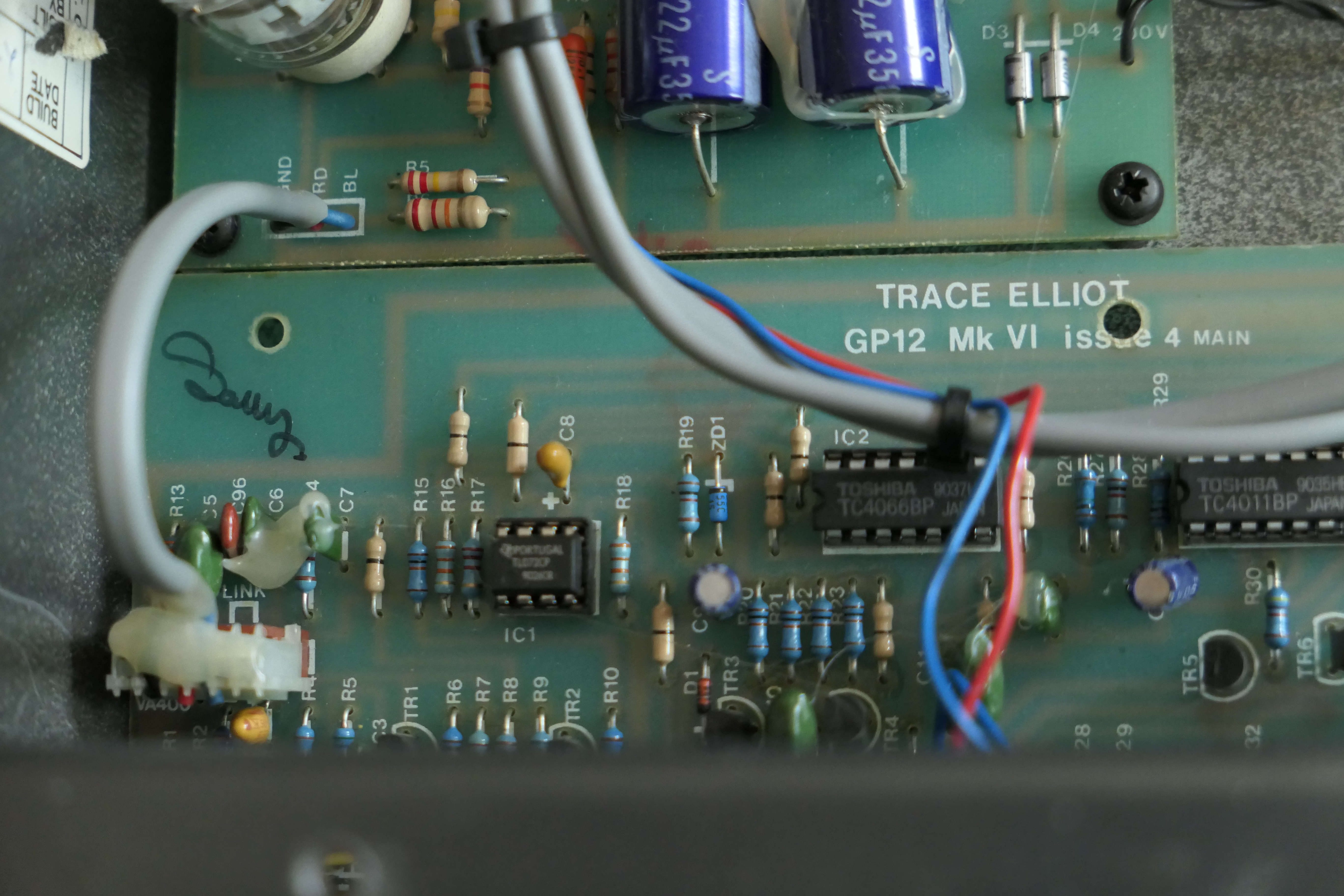
Below, this is a picture of my Series 6 GP12 AH200. Same preamp, but the connector is not populated (bottom left of the photo)

And with some other pictures with the PCB names


So I just opened it for a few pictures and to find one plastic washer from a jack connector that was rattling in the case.
Here is an overview, it has three boards, the classic GP12 preamp, the valve add-on and the rear connections circuit:
So it looks like the input valve is just an add-on that connects to the otherwise standard GP12 preamp through the "link" connector:
Below, this is a picture of my Series 6 GP12 AH200. Same preamp, but the connector is not populated (bottom left of the photo)
And with some other pictures with the PCB names
Last edited:

It has just arrived, I didn't test all inputs/outputs yet but it works well so far.
So I just opened it for a few pictures and to find one plastic washer from a jack connector that was rattling in the case.
Here is an overview, it has three boards, the classic GP12 preamp, the valve add-on and the rear connections circuit:
View attachment 5091684
View attachment 5091685 View attachment 5091686
So it looks like the input valve is just an add-on that connects to the otherwise standard GP12 preamp through the "link" connector:
View attachment 5091698
Below, this is a picture of my Series 6 GP12 AH200. Same preamp, but the connector is not populated (bottom left of the photo)
View attachment 5091704
And with some other pictures with the PCB names
View attachment 5091681 View attachment 5091682 View attachment 5091683
So I am pretty sure that means the preamp in the Valve Series service manuals includes the correct preamp schematic for the GP12XV and the GP12X is a "red herring."
AFAIK the Mk VI preamp schematic is shown "as connected" in the Mk VI AH series amps. The connection to the tube is not shown (or if it is I don't see it). So a technician may still have to puzzle the signal path out a bit.
Not unusual. I have found it hard to figure out how everything is interconnected in other TE service manuals. AFAIK, it's not unusual for some circuitry to not even be included in the schematic. For example my V8 has a magic eye power indicator tube, and I have found nothing that shows how it's wired into the circuit.
Yes exactly, the preamp is the one of the valve series quattra head manual, which is also the "usual" series 6 GP12 preamp (as written in the bottom right corner of the preamp schematic) with the added valve module (which schematic and connection points are a bit unclear yet).
Since the preamp is working and I am quite busy with various other things as well, I will not open and take everything apart just to reverse engineer the valve module and for once in my life, I'll follow the wise advice: "If it ain't broke, don't fix it."
Let me know if you want/need more detailed pictures, but I probably won't get pictures from the back side of the PCBs of anything not directly accessible.
Since the preamp is working and I am quite busy with various other things as well, I will not open and take everything apart just to reverse engineer the valve module and for once in my life, I'll follow the wise advice: "If it ain't broke, don't fix it."
Let me know if you want/need more detailed pictures, but I probably won't get pictures from the back side of the PCBs of anything not directly accessible.
I took a picture from the (same) preamp board on my Series 6 GP12 (AH200).
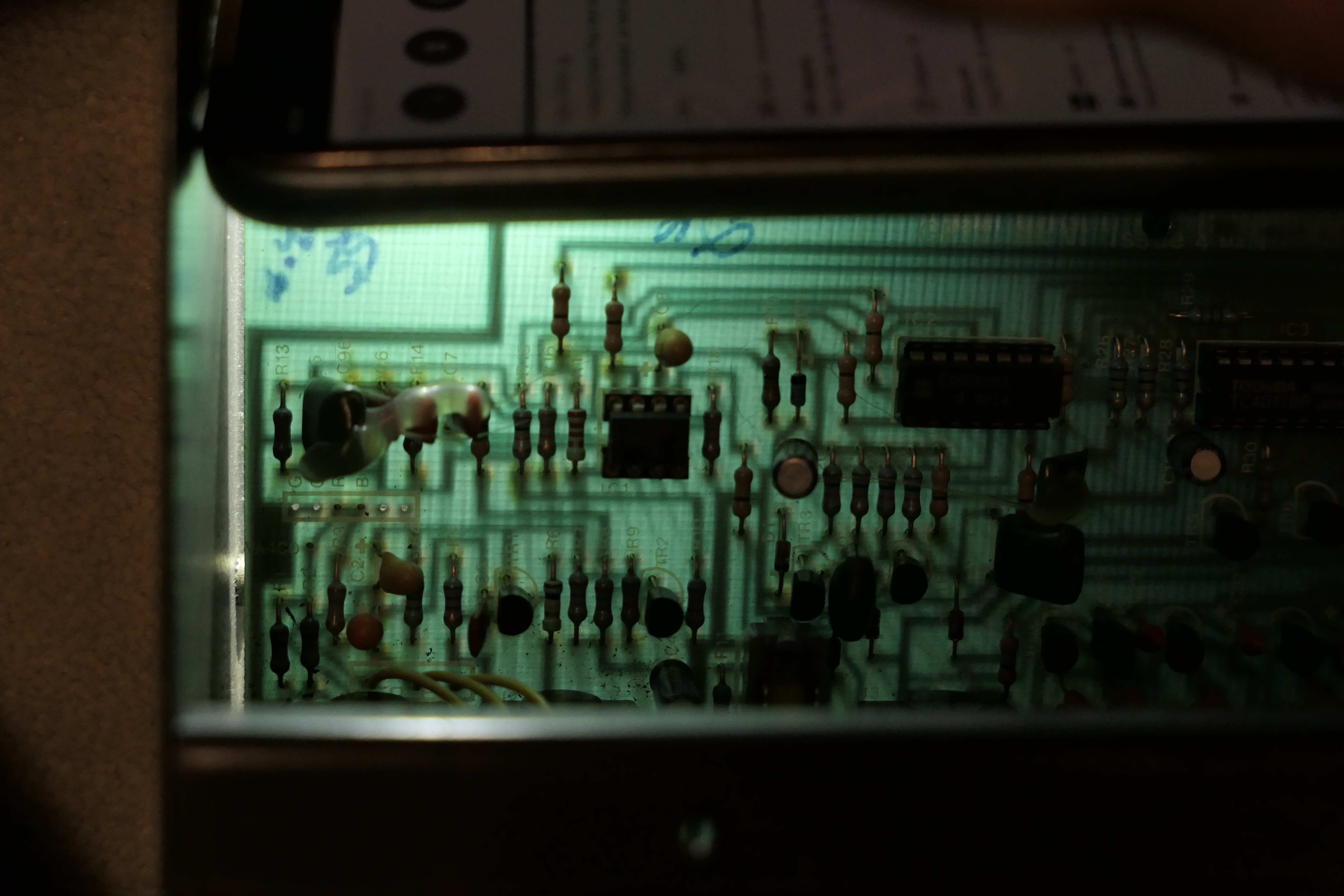
With a bit of backlighting, it is easy to see where the connector for the valve circuit (which is not populated here) sits in the circuit, between the R1/R2 junction and R3/Gain-Pot junction:
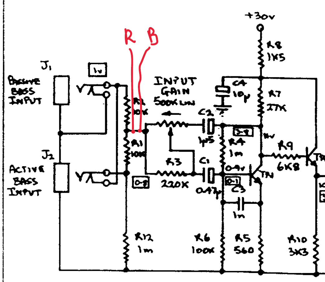
(from the preamp schematic on page 2 of the "Valve QuatHex SVC Man.pdf" file above)
"R" and "B" points are the Red and Blue signals on the page 3 of the service manual and are the "send" and "return" of the Valve module, so to speak (on the standard GP12, these two points are simply connected).
It seems the GP12-XV only adds a valve buffer using just half of the 12AX7.

With a bit of backlighting, it is easy to see where the connector for the valve circuit (which is not populated here) sits in the circuit, between the R1/R2 junction and R3/Gain-Pot junction:
(from the preamp schematic on page 2 of the "Valve QuatHex SVC Man.pdf" file above)
"R" and "B" points are the Red and Blue signals on the page 3 of the service manual and are the "send" and "return" of the Valve module, so to speak (on the standard GP12, these two points are simply connected).
It seems the GP12-XV only adds a valve buffer using just half of the 12AX7.
I took a picture from the (same) preamp board on my Series 6 GP12 (AH200).
View attachment 5095950
With a bit of backlighting, it is easy to see where the connector for the valve circuit (which is not populated here) sits in the circuit, between the R1/R2 junction and R3/Gain-Pot junction:
View attachment 5095949
(from the preamp schematic on page 2 of the "Valve QuatHex SVC Man.pdf" file above)
"R" and "B" points are the Red and Blue signals on the page 3 of the service manual and are the "send" and "return" of the Valve module, so to speak (on the standard GP12, these two points are simply connected).
It seems the GP12-XV only adds a valve buffer using just half of the 12AX7.
View attachment 5095951
Looks good. So, the GP12XV installs a connector with pins "R" and "B". On the regular GP12 there is jumper between these connections, so the signal passes straight through. On the GP12XV the jumper is cut. The input signal is sent out on R to a tube buffer (1/2 of the 12AX7). The output of the tube is returned back to the connector on B and continues through the normal signal path of the GP12. Now that you have worked it out, I see this is indicated fairly clearly on the Valve Series power amp schematic.
The second half of the 12AX7 is now the input of the power amp on the Valve series hybrids. A signal from the output of the GP12 card appears to drive the second triode. On most TE tube amps, it is driven by the first half of the 12AX7. So now you only have to puzzle out where the output signal from the GP12 is derived.
On the Hexa I believe the interconnect is the shield cable coming from the connector circled in yellow. I believe it is pin 2 of connector SK1.
As far as I can tell, it looks like the output from the GP12 is delivered to the next section in different ways depending on model.
For example on this image it looks like signal is sent to the I/O card on the back panel. I don't see any connection to the tube card, so maybe the second triode is not used on the preamp.
Yellow circle is SK1 on the I/O card. I believe the orange circle is SK1 on the preamp. On some models this appears to be where the output is connected. But on the GP12XV The yellow lines show were the signal leads are connected.
Their could possibly be some wires underneath the cards that go from the I/O board to the tube card.
Correct, in the XV the jumper between R and B is replaced by half a 12ax7.
From what I can see, the remaining half is left unused.
The orange circle is the connector that connects to the power/poweramp board of the amps containing GND, supply voltage, Preamp output and headphones signals.
The yellow circle (and line) is actually for the duplicated connections in the back (Footswitch, line in, send/return and DI are one to one replicated for convenience when rack-mounted). The rest of the I/O card takes care of the power supply conditioning and contains also the crossover circuit (no schematic found so far).
From what I can see, the remaining half is left unused.
The orange circle is the connector that connects to the power/poweramp board of the amps containing GND, supply voltage, Preamp output and headphones signals.
The yellow circle (and line) is actually for the duplicated connections in the back (Footswitch, line in, send/return and DI are one to one replicated for convenience when rack-mounted). The rest of the I/O card takes care of the power supply conditioning and contains also the crossover circuit (no schematic found so far).
Correct, in the XV the jumper between R and B is replaced by half a 12ax7.
From what I can see, the remaining half is left unused.
The orange circle is the connector that connects to the power/poweramp board of the amps containing GND, supply voltage, Preamp output and headphones signals.
The yellow circle (and line) is actually for the duplicated connections in the back (Footswitch, line in, send/return and DI are one to one replicated for convenience when rack-mounted). The rest of the I/O card takes care of the power supply conditioning and contains also the crossover circuit (no schematic found so far).
Take a look at some of the other images you posted of different models. I think you will see the orange connector provides audio out on some. For the GP12XV AFAIK it provides AC to feed a couple of power supplies and a ground.
The connector in the orange circle contains:
- GND
- preamp supply voltage ("from" power/IO-board "to" the GP12 preamp board)
- preamp audio output ("from" the preamp board "to" the power/IO board, in the amp versions this is the input signal for the power amp section, here, I guess this is the input for the crossover)
- headphones ("from" power/IO-board "to" the GP12 preamp board: in the amp versions at least, the phones is taken parallel to the cab output via resistor bridge, so I guess the I/O board also contains a rudimentary headphone amp circuit)
As can be seen on the photos above, the connector in the yellow circle contains:
- Line in (the thinner grey cable)
- Send-return (the thicker grey cable)
- Footswitch (the red and blue thin cables)
You can also see that the PCB traces going to the connector on the IO-board only go to the four connectors:
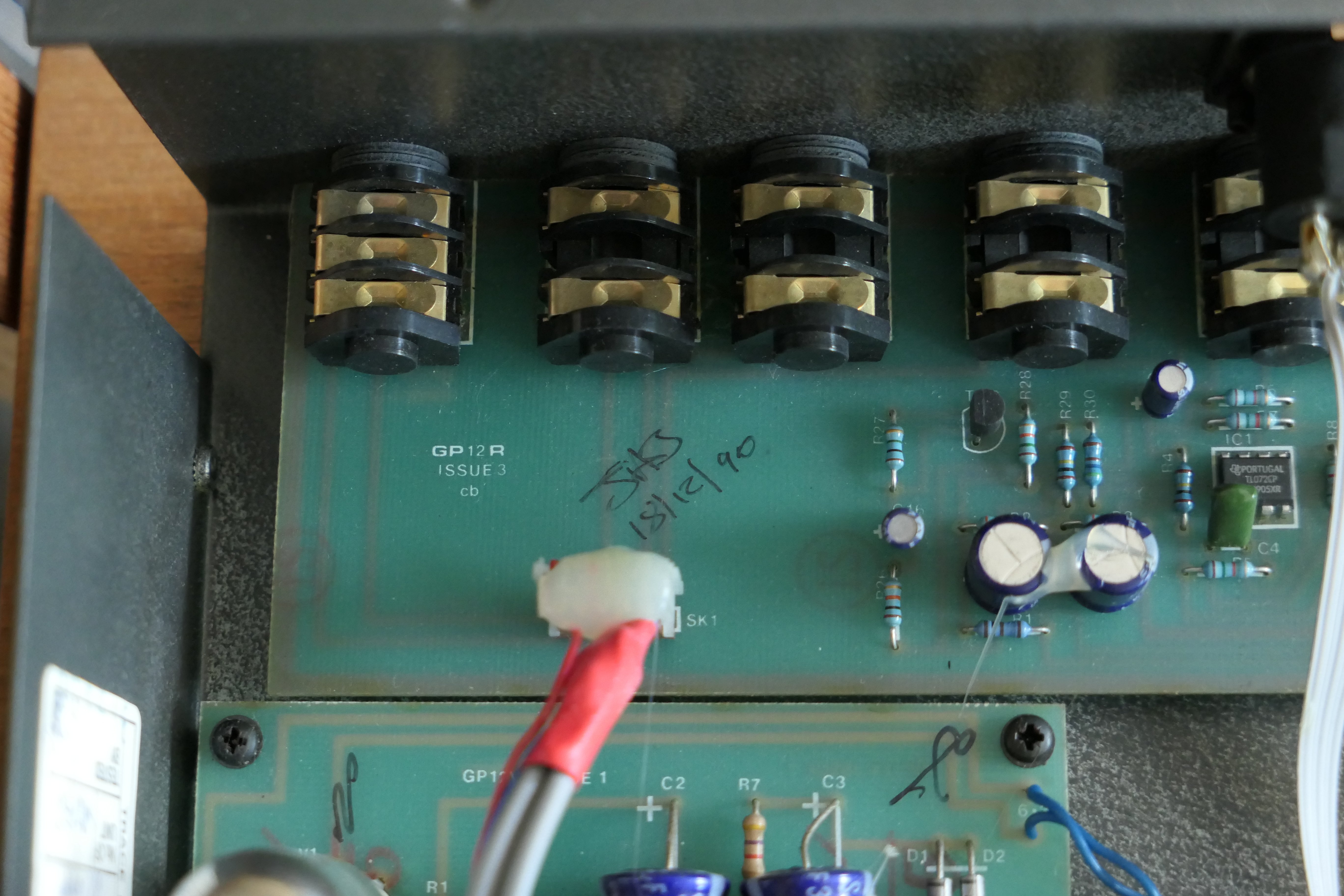
- GND
- preamp supply voltage ("from" power/IO-board "to" the GP12 preamp board)
- preamp audio output ("from" the preamp board "to" the power/IO board, in the amp versions this is the input signal for the power amp section, here, I guess this is the input for the crossover)
- headphones ("from" power/IO-board "to" the GP12 preamp board: in the amp versions at least, the phones is taken parallel to the cab output via resistor bridge, so I guess the I/O board also contains a rudimentary headphone amp circuit)
As can be seen on the photos above, the connector in the yellow circle contains:
- Line in (the thinner grey cable)
- Send-return (the thicker grey cable)
- Footswitch (the red and blue thin cables)
You can also see that the PCB traces going to the connector on the IO-board only go to the four connectors:
Latest posts
-

-

-
 Future Impact now available!! WAS: deep impact reissue!!! interested?
- Latest: Andras Szalay
-
 I didn't need it but I bought it anyway new (to me) cab day...
- Latest: S-Bigbottom
-
