• TalkBass has been independent since 1998. Add your voice.
    Create a free account to reply to discussions, view embedded media, and browse with fewer display ads.
    Join freeLog in
    Want zero display ads or expanded classifieds tools? Compare plans.

my adventure in cab building

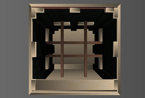
The cab is a larger ported 2x10 with 2 bp102s (8ohm each), volume and ports computed by eminance. I have bottom, top, back, and two sides together, with most of the bracing installed.
plan view top
10874341946_0bb75c27bd.jpg

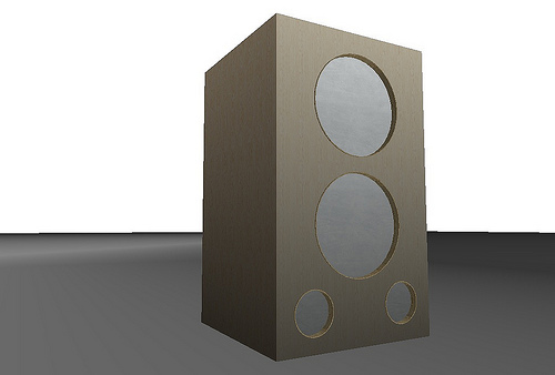
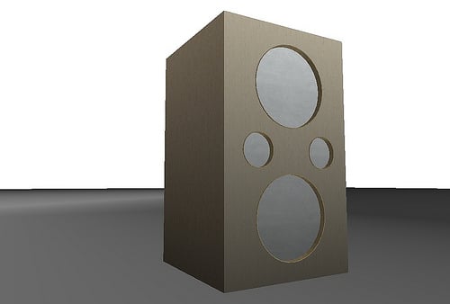
Next I'm cutting and routing the baffle holes and have narrowed the design to 3 choices.
10874627713_3073eb5d1b.jpg
#1
or
10874469844_1992c62603.jpg

#2
or
10874635693_20045be8d7.jpg

#3
What do you think?
Invalid Link RemovedPhotos and more questions to follow....
 
Well #1 looks the best, but...

If you expect to push the cab hard, #2 offers chimney-effect cooling (hot air goes out the top port, drawing cool air in the bottom port). The idea of placing ports both above and below the woofer magnet(s) was suggested to me by Jerry McNutt of Eminence, who may well have designed the BP102 to begin with.

If by any chance you plan to use flared ports, like Precision Ports, you might consider placing the ports on the rear of the enclosure, one high and one low, so that you can see the backs of the cones through the ports. You'll get midrange energy escaping through the ports, but the flares keep it from sounding harsh and edgy (sharp-edged ports introduce a lot of diffraction into any midrange that comes out the ports, and that can sound harsh at high SPLs). This way, your drummer will have a bit better chance of hearing your overtones and being able to tell what you're doing.

These two techniques are things I do in my commercial bass cabs, not that that bestows any particular credibility on them.

And with the ports on the back, you can get away with plugging one or both with an expandable plumber's test plug, if you find yourself in a really boomy room. Yeah, I incorporate that too.
 
In theory...port location shouldn't matter as the frequencies they're operating at are not directonal. But, as is Dukes examples of rear-firing midrange and cooling, sometimes it does matter.

As far as side ports, I wouldn't think you'd have much of the midrange leak thing going on. Biggest concern would be keeping a few inches distance betwen it and the wall or other cabs so as not to block or constrict the ports.
 
Breaking out the old router and making a jig and testing bits, any more suggestions, comments on hole placement. I have to decided to place ports in front, probably in the alignment #2 above. What are best distances between drivers and walls, ports and walls, drivers and ports. Do the above alignments look o.k.? The drivers are 3 inches from left wall and 1 inch between outside edges of drivers. ports are 2" from top and side and bottom and side. and about 2" from outside edge of driver rim.
 
I think the general rule of thumb of clearance for ports is 1 diameter, i.e. 3" clear between port and wall, both at the end and along the side for a 3" port.

Another option for speaker / port arrangement, is similar to #2, but with the top half flipped. From top to bottom: speaker in center-ish, port on the right, speaker in ceneter-ish, port on the right.
 
In theory...port location shouldn't matter as the frequencies they're operating at are not directonal. But, as is Dukes examples of rear-firing midrange and cooling, sometimes it does matter.
A simple felt interposer, one diameter away from the port opening will circumvent any midrange radiation from the driver exiting the port.
This is typical carpet felt, 1/2" or so, and has no effect on the internal cabinet volume.
 
The design I am following suggested straight ports. Does changing that to flared change length?
Also, Pictures of build in progress on:
Invalid Link Removed

Flared ports do change the effective length slightly. Basically, the air on the inner half of the flare (closest to the straight length of pipe) belongs to the port and the outer half belongs to the outside air (or internal cab air on the back/inside-the-box end).

They do offer some other benefits, such as less air turbulence, so you can get away with slightly less port area for a given tuning without chuffing. And in a Duke design where some midrange escaping is desirable, less diffraction/more "musical" sound from the rear-escaping midrange tones.
 
A simple felt interposer, one diameter away from the port opening will circumvent any midrange radiation from the driver exiting the port.
This is typical carpet felt, 1/2" or so, and has no effect on the internal cabinet volume.

That's a pretty cool trick for compact cabs with ports behind the driver. I hadn't thought of it, but it would basically damp the mids before they have a chance to exit.....cool.
 
10906486094_65c3c63d86_z.jpg

does this look right?

But seriously, it's so great that an amateur like myself get get advice and information from experienced practitioners and seasoned professionals, I still can't quite believe it. Go TALKBASS!
Anyway, after much penciling and maneuvering of hole placement possibilities this is the arrangement I feel most comfortable with, structurally. And, also seriously, The tin can is exactly 4 inches, could you really use this as a port tube?
Comments from other amateurs also welcome.
 
I've used cardboard tube and pvc pipe that worked fine. I suppose the can could too, as long as it doesn't vibrate/resonate/make noise when the woofers get pumping. The little ridges in it would cause more air turbulence, so make sure you've got enough port area. Not pushing them to the chuffing limit.
 
Go to a yard that sells sprinkler supplies.
You can acquire PVC of all diameters here, and maybe a scrap piece on the cheap.
White PVC 40 is ubiquitous and comes in all sizes.
Cut the vent holes to match the piece you are using... not a coffee can.

I'm surprised you are cutting holes after the box is assembled...
One goof, and a large "aw sh*t" later, and you start over from the top.
I use a Jasper jig on my plunge router for accurate cuts.

You will find the tuning is close, but not accurate.
Do not seal your vents until it is final-tuned, damping material in place, and 100 hours on the drivers.

Break in new drivers at 10 volts or less, 30 Hz.
Open air, on the bench will do.
This will be inaudible to you, but your dog will hate you.
The low voltage will break in the suspension, without worry of damage from over excursion.
 
Finishing bracing, getting router set up(making jig), and beginning lining and damping interior.
10940936773_50f9111b28.jpg

Full set of build in progress pictures on Flickr
And, again, thanks for all the info, I'm keeping track of it all.
I spent a couple decades in the construction business, and I am currently involved in an ongoing home remodeling and add on project, and am using my experience in that field where applicable, as well as using left over materials as much as possible. Up to now the only thing I've had to buy are the drivers, but, alas, today I had to go to the hardware store.
 
So I've read a few books, scoured this forum and other audio acoustic type forums, mixed all that information up in my brain and come up with this concoction for lining and damping so far.
What do you think people?
10965827436_b68acf2fb4.jpg

will add fiberglass panels on top of rubber, and maybe some screen or fabric over that to keep the fiberglass dust down-after I fit the baffle and drill holes for electrical stuff.

so lining is composed of:
laminations in plywood
pva glue size over plywood
asphalt felt paper gorilla glued to panels
rubber roof flashing gorilla glued to tarpaper

now back to routering, the router is my least favorite power tool.

complete photo record of cab build on flickr
 
The plywood laminates will shrink the box by their thickness. Plain old quilt batting or mattress foam will do fine for damping. Anything you can build up to 1"-2" thickness that can still easily pass air through/breathe through. Fiberglass or wool will also work.


Your bracing "ribs" would be stiffer if they were fastened perpendicular to the panels, but, with the crossbracing you're using, might work out fine as is.
 
Nice job!

The most critical place to brace is the middle of that front baffle. If you can figure out a way to connect that rigidly to the rear panel, or better yet to the bracing junction there in the middle which then connects to all four vertical panels, imo that would be a good idea. I'd even be tempted to reinforce the areas in between the woofer and port cut-outs on the front baffle.

Crude analogy: Imagine pushing off the side of a building. Now imagine pushing off of a hanging rope. You get a much better push off of the solid building. Likewise, your woofer gives the air a more solid push (better impact) from a very rigid front baffle. This is an area where some manufacturers cut corners, so it's an opportunity for you to build a better box than many people buy.