Ok, so I just got a new Bassballs Nano pedal and would like to do the external trimpot mod. I have ordered a pair of 10K linear 9mm pot (smallest I could find) from Small Bear Electronics and I am hopeful they will fit. It's been done before, I've seen it on TB.
So, yeah, I did do a search, and came up with a few threads that have been of some help :
Bassballs External Frequency pots mod?
http://www.talkbass.com/forum/showthread.php?t=558116
Bassballs external trimpot mod? Anyone know how?
http://www.talkbass.com/forum/showthread.php?t=327439
Also Bassballs related are these two websites:
Topopiccione Electronics - Electro-Harmonix BassBalls (schematics and other stuff)
http://topopiccione.atspace.com/PJ08EHBassBalls.html
L'atelier de Basstrya (French how-to mod the old version)
[Invalid or Expired Link Removed]
But I'm still a little confused of how to execute this mod. I just want to make sure I get everything right. And in the process I could write a nice little write-up on how to mod your Nano Bassballs. But I need your help! Here are some pics I took of my Balls (!).
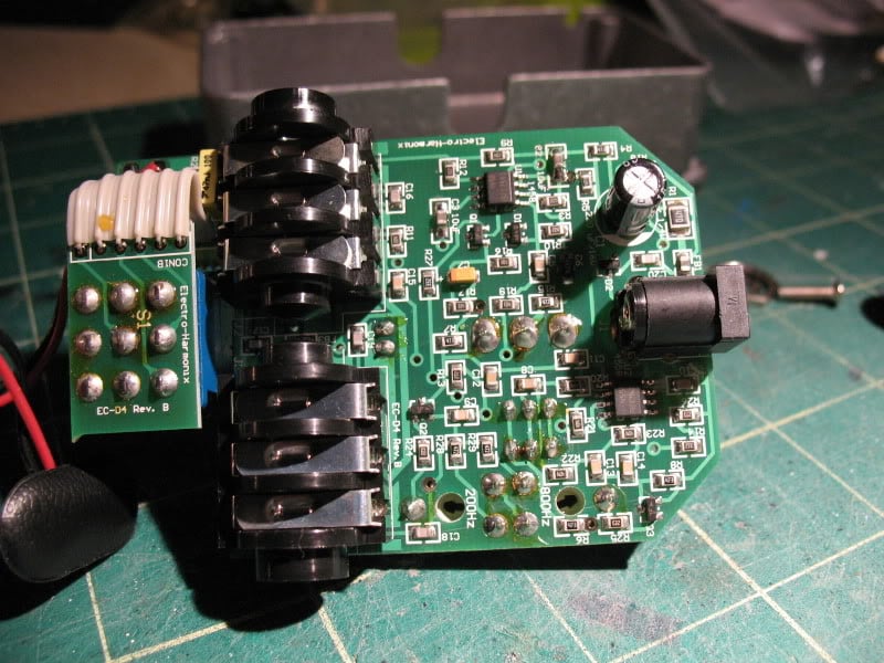
This is the back, i.e. you see this when you pop out the rear cover:
This is the top. You can clearly see two trimpots at the top right.
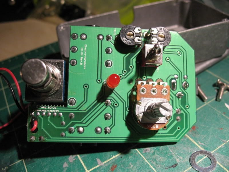
Here is a close-up of the back, right where the trimpots are.
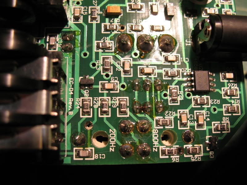
So all the threads I have seen say to remove the 5k trimpots and the 4,7k resistors in series with them (which, if I understand correctly, are R28 and R29 on the PC board, right?) and replace them with 10k linear pots.
Question 1 : do I have to fill the gap left by the removed resistors? If you look at [Invalid or Expired Link Removed]from the French site, you will notice that he's left the gap. If I understand correctly, the R28 & R29 resistors are linked on one side to the filter circuit, on the other side to the ground. So leaving the gap makes sense. And connecting the common ground from the new external pots to the "left" pin of R28 (the one above the R of R28) will work?
Question 2 : Am I getting this right : Middle lugs of new pots (pinkish wire on French site) each go to the "lone" pin of the old trimpots on PCB (leading to R24 for 200Hz and R25 for 800Hz). Left lugs of the new pots (blue wire on French site) each go to PCB pins that are linked together on the Nano (the one above the 2 of 200Hz and the one below the z of 800Hz).
Help much appreciated!
So, yeah, I did do a search, and came up with a few threads that have been of some help :
Bassballs External Frequency pots mod?
http://www.talkbass.com/forum/showthread.php?t=558116
Bassballs external trimpot mod? Anyone know how?
http://www.talkbass.com/forum/showthread.php?t=327439
Also Bassballs related are these two websites:
Topopiccione Electronics - Electro-Harmonix BassBalls (schematics and other stuff)
http://topopiccione.atspace.com/PJ08EHBassBalls.html
L'atelier de Basstrya (French how-to mod the old version)
[Invalid or Expired Link Removed]
But I'm still a little confused of how to execute this mod. I just want to make sure I get everything right. And in the process I could write a nice little write-up on how to mod your Nano Bassballs. But I need your help! Here are some pics I took of my Balls (!).
This is the back, i.e. you see this when you pop out the rear cover:
This is the top. You can clearly see two trimpots at the top right.
Here is a close-up of the back, right where the trimpots are.
So all the threads I have seen say to remove the 5k trimpots and the 4,7k resistors in series with them (which, if I understand correctly, are R28 and R29 on the PC board, right?) and replace them with 10k linear pots.
Question 1 : do I have to fill the gap left by the removed resistors? If you look at [Invalid or Expired Link Removed]from the French site, you will notice that he's left the gap. If I understand correctly, the R28 & R29 resistors are linked on one side to the filter circuit, on the other side to the ground. So leaving the gap makes sense. And connecting the common ground from the new external pots to the "left" pin of R28 (the one above the R of R28) will work?
Question 2 : Am I getting this right : Middle lugs of new pots (pinkish wire on French site) each go to the "lone" pin of the old trimpots on PCB (leading to R24 for 200Hz and R25 for 800Hz). Left lugs of the new pots (blue wire on French site) each go to PCB pins that are linked together on the Nano (the one above the 2 of 200Hz and the one below the z of 800Hz).
Help much appreciated!