• TalkBass has been independent since 1998. Add your voice.
    Create a free account to reply to discussions, view embedded media, and browse with fewer display ads.
    Join freeLog in
    Want zero display ads or expanded classifieds tools? Compare plans.

Nano Bassballs Trimpots Mod

Ok, man. Ask and you shall receive.

I was reminded of a few of the things I did when rehousing this thing. The first is to use a Hammond 1590C box. This box is big enough to put the switches and things directly above the PCB which saves a ton of lateral space. The second is to butcher the plate the PCB was mounted to to use the arms as a brace inside the 1590C. This allowed me to keep the jacks mounted to the PCB without feeling like it was going to be unsupported. Perhaps this was overkill and it didn't matter, but I did it anyway. The third was abandon battery usage. I could probably cut a battery drawer into it, but I don't care to so I'm not going to.

Here's the PCB.
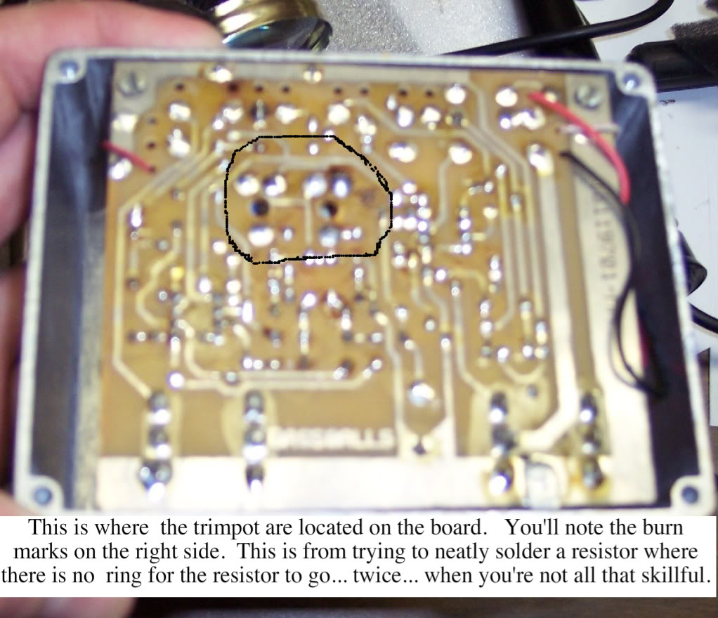
BallsPCB.jpg


Here's where I swapped the trimmers for wires. I had to jumper a resistor from where that orange wire dives into the PCB over to a different solder point. This was a major PIA, but I got it done. This is where EHX really got their moneys worth hiring monkeys to design their PCB layout. Scientist monkeys.:scowl:
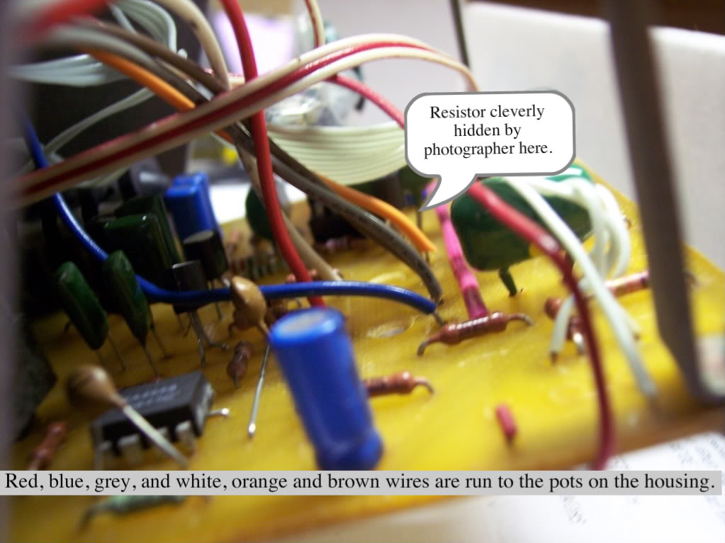
Ballsguts.jpg


I also changed out their monolithic distortion switch for a simple spdt toggle. I didn't change to TBP or Boss power jack because I didn't need to and I figured if I do I can dig into it later.

 
why would EHX have put trimpots there rather than just regular resistors if not for you to mess around with them?

Trimpots in almost any circuit are not meant for user adjustments but to allow the mfr or a repairman to fine tune the circuit.

If EH had really intended for users to tweak the pots they would have mentioned it in the manual or just provided knobs in the first place.
 
Trimpots in almost any circuit are not meant for user adjustments but to allow the mfr or a repairman to fine tune the circuit.

If EH had really intended for users to tweak the pots they would have mentioned it in the manual or just provided knobs in the first place.
The old "if we were meant to fly we would have wings" reasoning may not always be valid. I have the BassBalls modded by Soloman and while it is no longer a BassBalls it is a truly beautiful thing to tweak a lot more fun & synth like which may or may not be your thing.
 
Necroposting this thread to ask a simple question:

I'm a set-and-forget kind of pedal user for the most part. I don't much need to mod my Bassballs like shown in this thread, but I want to adjust the sound. Which trimpot do I turn which way to pull out the 'whistle' overtone from the effect? I'm assuming, based on the demos I have seen with the knob mod, that it would be the pot closer to the switch (800hz?), turned counterclockwise when looking at it from the open back. Y/N?

EDIT: I don't have the BB in my hands yet, otherwise I'd probably just experiment, but I don't want to mess with both if only one is needed to do this one thing.

Thanks!
 
Last edited:
So since this post is a little out of date I was hoping for some insight on using these 10k pots from amazon. I kind of like how the wires are already on and it comes with knobs. I figured I’d crimp off the connector and solder the wire directly to the board, remove the resistors, solder with jumpers, drill
some holes and I’m done.

10K OHM Linear Taper Rotary Potentiometer B10K Pot with Knob and 3-Pin JST-XH2.54 Connector Lead(pack of 2) https://www.amazon.com/dp/B071X4DKV7/ref=cm_sw_r_cp_api_A7dXAbWT5EZFN
 
As an Amazon Associate, TalkBass may receive commissions from qualifying purchases made via links on this site.
So since this post is a little out of date I was hoping for some insight on using these 10k pots from amazon. I kind of like how the wires are already on and it comes with knobs. I figured I’d crimp off the connector and solder the wire directly to the board, remove the resistors, solder with jumpers, drill
some holes and I’m done.

10K OHM Linear Taper Rotary Potentiometer B10K Pot with Knob and 3-Pin JST-XH2.54 Connector Lead(pack of 2) https://www.amazon.com/dp/B071X4DKV7/ref=cm_sw_r_cp_api_A7dXAbWT5EZFN

Been a long time since I did this mod, but from memory there wasn't much room in the enclosure. Might work fine though.
 
As an Amazon Associate, TalkBass may receive commissions from qualifying purchases made via links on this site.
Hola queria consultarte sobre el esquema del pedal pero de su version nano yo tengo uno y cuando lo reviso me esta fallando el capacitor ceramico #17
Espero que alguno de ustedes me pueda ayudar en algo, gracias
 
So I got my pots from Small Bear in the mail today! I immediately set to work...

I started by drilling two 9/32" holes in my casing about 15 mm above and below the distortion switch (center of switch to center of pots). It's actually a little less than 15 mm below the switch... more like 13 mm. It's not exact science, so make your own test-fits and measurments before drilling!

Then on the the PCB -- I removed the trimpots as well as R28 and R29. I used an unsoldering braid which was real handy. I did burn the PCB a little, nothing too bad.

View attachment 1511251

Then I took both my 9mm Alpha pots and soldered overly long pieces of solid 20-gauge wire with the plastic insulation removed. It is necessary to use solid wire so the pot won't move around as much as with stranded wire, yet you will have some "wiggle room". I also filled flat the little notch on the base of the shaft. You need every mm you can spare in this mod!

View attachment 1511252

I then fitted the new pots to the board and soldered them. Of course, you have to cut the overly long leads afterwards!

View attachment 1511253

I also soldered a set of jumpers where R28 and R29 used to be. Small pieces of solid 20-gauge wire did the trick.

View attachment 1511254

Re-assembly, test run, knobs -- here's how it looks now.

View attachment 1511255

--------------

I've seen this mod done otherwise. One person here on TB had the pots on either side of the LED. This works too, but I wanted my new knobs to be as far as the stomp switch as possible! It does make the top of the pedal a bit crowded, however. Might not be that good an idea if you have really big fingers... lol!

So yeah, there you have it. External pots on a Nano. It's a simple mod that makes this pedal a lot more versatile. Some settings are pretty useless, and at some positions there is a slight volume drop. But it does make tweaking this puppy a lot easier!

Enjoy!

You have the scheme, I need to know the value of capacitor c17
 
Alguien que h
Ok, so I just got a new Bassballs Nano pedal and would like to do the external trimpot mod. I have ordered a pair of 10K linear 9mm pot (smallest I could find) from Small Bear Electronics and I am hopeful they will fit. It's been done before, I've seen it on TB.

So, yeah, I did do a search, and came up with a few threads that have been of some help :

Bassballs External Frequency pots mod?

Bassballs external trimpot mod? Anyone know how?

Also Bassballs related are these two websites:

Topopiccione Electronics - Electro-Harmonix BassBalls (schematics and other stuff)
Topopiccione Electronics Inc. - Electro-Harmonix BassBalls

L'atelier de Basstrya (French how-to mod the old version)
[Invalid or Expired Link Removed]

But I'm still a little confused of how to execute this mod. I just want to make sure I get everything right. And in the process I could write a nice little write-up on how to mod your Nano Bassballs. But I need your help! Here are some pics I took of my Balls (!).

This is the back, i.e. you see this when you pop out the rear cover:

View attachment 1504961

This is the top. You can clearly see two trimpots at the top right.

View attachment 1504962

Here is a close-up of the back, right where the trimpots are.

View attachment 1504963

Entonces, todos los hilos que he visto dicen que elimine los potenciómetros de 5k y las resistencias de 4,7k en serie con ellos (que, si entiendo bien, son R28 and R29 on the PC board, right?) and replace them with 10k linear pots.

Pregunta 1: ¿tengo que llenar el espacio dejado por las resistencias eliminadas? Si miras[Invalid or Expired Link Removed]from the French site, you will notice that he's left the gap. If I understand correctly, the R28 & R29 resistors are linked on one side to the filter circuit, on the other side to the ground. So leaving the gap makes sense. And connecting the common ground from the new external pots to the "left" pin of R28 (the one above the R of R28) will work?

Pregunta 2: ¿Estoy entendiendo esto bien? Las orejetas del medio de los potenciómetros nuevos (cable rosado en el sitio francés) van cada uno al pin "solitario" de los potenciómetros de ajuste antiguos en la PCB (que conduce a R24 para 200 Hz y R25 para 800 Hz). Las orejetas izquierdas de los nuevos potenciómetros (cable azul en el sitio en francés) van cada una a los pines de la PCB que están conectados entre sí en el Nano (el que está arriba del 2 de 200 Hz y el que está debajo de la z de 800 Hz).

¡Se agradece mucho la ayuda!
Hola, alguien que respondió esto Hello, someone who has answered this post that has the schematic of this particular pedal, It has the different things, the capacitors, the resistors and the scheme