
• TalkBass has been independent since 1998. Add your voice.
    Create a free account to reply to discussions, view embedded media, and browse with fewer display ads.
    Join freeLog in
    Want zero display ads or expanded classifieds tools? Compare plans.

Please! help me with a DPDT wiring diagram. ATK300

Hey guys

I'm having a headache

I'm trying to wire the atk300 without the preamp and replacing the original switch and little board with caps with a 3way dpdt.
Basically going from the pickup and straight to dpdt switch and then to the output jack.

I tried a few approaches - but I get no sound coming out of the dpdt switch at all.
The pickup works fine when wired straight to the jack, so I probably dont understand how to wire dpdt correctly and my brain is not able to process it.

Here's the original wiring.
SUm_Xxia58Q.jpg


7xWwlRXRNFA.jpg


SO, I'm loosing the preamp and the switch, and replacing it all with just the DPDT 3-way switch. I know some people did it in the past and there are vids on youtube and some info here on TB
Here's how it should work:
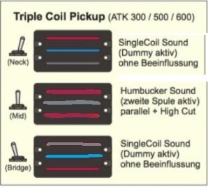
1.neck+dummy
2.neck+bridge parallel (humbucker)
3.bridge+dummy
P2x51izpdF8.jpg


Here's the detailed desription of the pickup and basically how to wire it, but theres no info on how to do it with a dpdt switch

atkpickupwiringdiagram-jpg.jpg

Here's how the pickup is wired to the "character switch" in my ATK305:

Traditional: red is hot, black is grounded, white and blue are floating. Only the neck coil senses the strings, for a single-coil sound. However, the dummy coil provides some noise reduction, and a low pass filter removes some highs for a more traditional sound.

Middle position: same as Traditional, but with the low-pass filter bypassed for a brighter tone. A little more noise gets through with the LPF bypassed.

Attack position: red and green are hot, black and white are grounded. Both ends of the dummy coil are grounded, and the bridge and neck coils are connected in parallel. This setting behaves like a conventional humbucker, but with a little wider frequency response because of the parallel connection.


Jazz bass fans can add a useful tone, by installing a second switch before the character switch. Connecting green hot and white to ground (red/blk floating), gives single-coil style bridge pickup tones. The dummy coil is still active, for some noise reduction.


Could anyone be so kind and paint some rough scheme for me because I have no experience with wiring at all and this drives me nuts!
I'd be forever grateful, it should be simple enough for a person with experience.

Huge thanks!
 
  • Like
Reactions: gregmon79
I don't think it can be done, but someone will probably come along & prove me wrong soon.

This is the configuration of a switch like that:
225891618.jpg

I tried to work it out as a sort of brain teezer.
If you want bridge+phantom on in the down position (position 1), then you need:
white = 6
green = 3
ground = 5
output = 2

now for neck+phantom in position 3 (toggle up):
black = 4
red = 1

Here's where the problem lies, in the middle position only the bridge coil will be engaged.

We could try it another way, starting with the middle position:
white = 5
black = 4
green = 3
red=2
this would have the bridge+neck in parallel & shunt the phantom coil

Now the predicament is neither of the other two positions will work.

There might be a way to do it with jumpers that I can't conceive, but I think you need another pole.
 
I don't think it can be done, but someone will probably come along & prove me wrong soon..
thank you!!
yes I'm basically having the same problem, it looks like there are not enough poles, maybe this guy on youtube used single coils without a dummy coil?


I decided to try and wire it on 2 dpdt switches - on-on-on and on-on
this way I have neck+dummy, neck single, bridge+dummy on the first ON-ON-ON switch, and the second one switches the mid poistion to parallel outer coils(humbucker)
Does it look correct?
3sqXZiMD7HY.jpg
 
I don't think it can be done, but someone will probably come along & prove me wrong soon.

This is the configuration of a switch like that:
View attachment 2893754
I tried to work it out as a sort of brain teezer.
If you want bridge+phantom on in the down position (position 1), then you need:
white = 6
green = 3
ground = 5
output = 2

now for neck+phantom in position 3 (toggle up):
black = 4
red = 1

Here's where the problem lies, in the middle position only the bridge coil will be engaged.

We could try it another way, starting with the middle position:
white = 5
black = 4
green = 3
red=2
this would have the bridge+neck in parallel & shunt the phantom coil

Now the predicament is neither of the other two positions will work.

There might be a way to do it with jumpers that I can't conceive, but I think you need another pole.
Try putting a jumper between 1 and 6, then neck is on for up or down. Dummy is on 3 and is on in up or middle. Bridge on 4 and is on when in middle or down. 5 gets jumped to 2, which is your output, ground goes to a pot back and shield is of course shield.
 
Last edited:
There's no point in engaging the dummy coil with the bridge coil.

The dummy coil is wound reverse in relation to the neck coil, thus when both are engaged it cancels hum.

The bridge coil is also wound reverse in relation to the neck coil, thus when both are engaged it cancels hum.

Engaging the dummy coil with the bridge coil won't cancel hum. It's going to be noisy. Probably no worse than a typical jazz bass with either pickup soloed, but noisier than a humcancelling circuit.
 
  • Like
Reactions: Killed_by_Death
There's no point in engaging the dummy coil with the bridge coil.

The dummy coil is wound reverse in relation to the neck coil, thus when both are engaged it cancels hum.

The bridge coil is also wound reverse in relation to the neck coil, thus when both are engaged it cancels hum.

Engaging the dummy coil with the bridge coil won't cancel hum. It's going to be noisy. Probably no worse than a typical jazz bass with either pickup soloed, but noisier than a humcancelling circuit.
I wonder if the output will be higher with the bridge and dummy engaged together too; not sure how that works any more, it's been too long. Isn't the current additive when in phase?
 
Last edited:
red = 3
green = 4
white = 6
1-6 jumped
2-5 jumped, output
black = to ground on a pot
shield = DUH!
That will give you exactly what you want.
thanks!
like this?
Ye1wSzDrsAY.jpg

but in this case it results in:
1. dummy coil (red+white to output, which causes neck coil to short circuit and leaves us with white wire and a single dummy coil)
2. 3 coils (white in limbo)
3. bridge+dummy parallel
if the black wire is always going to ground
maybe you started with cofusing white with black and some problems occured from it later down the road?
but thanks nonetheless!
what do you think about this diagram btw?
3sqxzimd7hy-jpg.jpg


I wonder if the output will be higher with the bridge and dummy engaged together too; not sure how that works any more, it's been too long. Isn't the current additive when in phase?
yes that is correct, even if its still noisy, higher output from dummy coil should balance both neck and bridge positions volume-wise.
 
I wonder if the output will be higher with the bridge and dummy engaged together too; not sure how that works any more, it's been too long. Isn't the current additive when in phase?
The dummy coil has no magnets, so it doesn't pick up any string vibration - it only picks up hum. So, wired out of phase with a regular single coil pickup, the hum is cancelled out.

Wired in phase with a regular single coil, the hum will be doubled. Not a good thing.......
 
  • Like
Reactions: Killed_by_Death
The dummy coil has no magnets, so it doesn't pick up any string vibration - it only picks up hum. So, wired out of phase with a regular single coil pickup, the hum is cancelled out.

Wired in phase with a regular single coil, the hum will be doubled. Not a good thing.......

here's the info from 2 different sources:

Neck coil: 5.5k
Dummy coil: 5.1k
Bridge coil: 5.2k

atkpickupreadings-jpg.jpg


confirmation is in this message, and further down the thread
ATK305 second pickup options?
 
Last edited:
thanks!
like this?
View attachment 2896006
but in this case it results in:
1. dummy coil (red+white to output, which causes neck coil to short circuit and leaves us with white wire and a single dummy coil)
2. 3 coils (white in limbo)
3. bridge+dummy parallel
if the black wire is always going to ground
maybe you started with cofusing white with black and some problems occured from it later down the road?
but thanks nonetheless!
what do you think about this diagram btw?
View attachment 2896007


yes that is correct, even if its still noisy, higher output from dummy coil should balance both neck and bridge positions volume-wise.
You're asking me for my opinion after I have already given you bad information? 1) You should know better. 2) I'm clearly in over my head on this, so I'll back out of this thread.
 
This simple mod would eliminate the preamp
SUm_Xxia58Q.jpg

but since you are trying to change the functions of the switch, I'll have to do a little mapping and thinking before I show you how to wire the 3 position DPDT switch in the matter of how you want it. I'll try to get that done later today, depending on how soon I can get done with work.
 
The value of the coil's resistance means nothing if it doesn't have a magnet in it to produce a signal from the string vibration.
You don't want the bridge & phantom coils on at the same time.

add: This might be false, because using the white wire as ground would reverse the polarity of the dummy coil.

I'm clearly in over my head on this, so I'll back out of this thread.

I think we both are. Where's line6man when we need him?
He seems to know a lot about switches.

Hey, at least you reminded me last weekend about using a voltmeter to check for continuity.
I'm so used to checking for continuity in passive circuits that I completely forgot that approach.
 
Last edited:
  • Like
Reactions: sissy kathy
You don't want the bridge & phantom coils on at the same time.

What is the reasoning for that? Does it hurt to have the noise canceling feature of the dummy coil?

Here is what I was thinking for what the switch needs to do but I used the dummy with the bridge:

Neck Selection:
Red - Signal
White - Floating
Black - Gnd
Grn - Floating (or Gnd)

Both Selection:
Red - Signal
White - Gnd
Black - Gnd
Grn - Signal

BridgeSelection:
Red - Floating (or Gnd)
White - Gnd
Black - Floating
Grn - Signal
 
The dummy only works for canceling noise when engaged with the neck coil. If you engage it with the bridge pickup you're just doubling the noise, not canceling it.
Read BruceWane's posts on this.
Makes sense. I didn't catch that post.

Neck Selection:
Red - Signal
White - Floating
Black - Gnd
Grn - Floating (or Gnd)

Both Selection:
Red - Signal
White - Gnd
Black - Gnd
Grn - Signal

BridgeSelection:
Red - Floating (or Gnd)
White - Floating (or Gnd)
Black - Gnd
Grn - Signal