• TalkBass has been independent since 1998. Add your voice.
    Create a free account to reply to discussions, view embedded media, and browse with fewer display ads.
    Join freeLog in
    Want zero display ads or expanded classifieds tools? Compare plans.

Router Planing Fixtures

Bruce Johnson

Gold Supporting Member
Commercial User
Feb 4, 2011
16,057
56,933
70
Fillmore, CA
www.xstrange.com
Disclosures
Professional Luthier
We've talked before about Router Planing; using routers and fixtures to cut boards down to thickness and make them precisely flat. I was just doing some router planing last night, so I shot a few quick pictures to show all of you one of these fixtures and how it works.

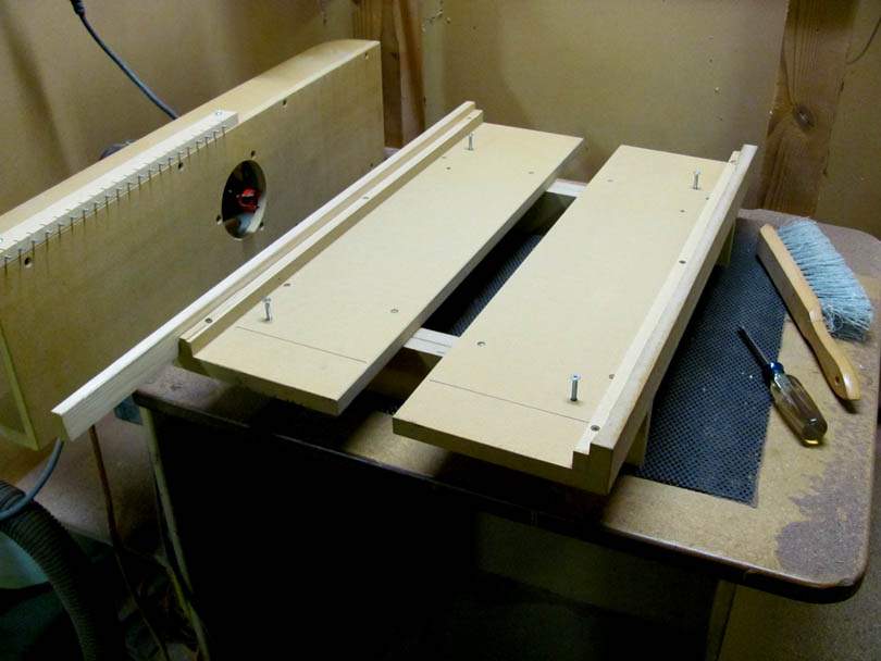
This is a wide version of a planing fixture, which I built specifically to cut the tops and backs of my Scroll Bass bodies. I make them from 4/4 poplar or walnut; two matched pieces 7 1/2" x 22", jointed and edge glued with epoxy into a 15" wide x 22" long board. I use this fixture to take that glued board down in thickness from 0.810" to 0.700", making it flat and taking out any cupping.

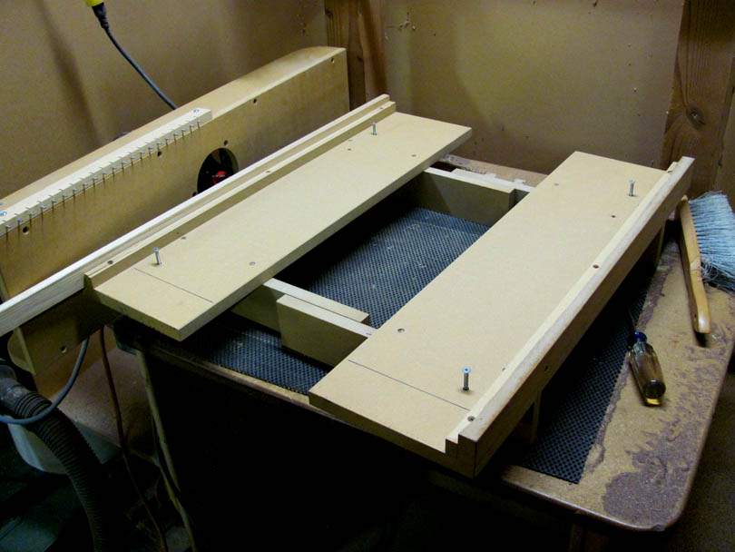
The fixture itself is made of MDF. It's two halves which fit together and make it adjustable in width. The body board can be clamped in the fixture, squeezing it between the two halves with two clamps from underneath.

On these Scroll Bass body blanks, I pre-drill four holes in the corners at standard locations. The holes are counterbored and countersunk on both sides. Four 10-32 screws thread down into T-nuts in the fixture, to clamp the board down. I rout the inside surface of the board first, cleaning it up and making it flat. Then I flip it over and rout the outside surface to bring it down to the final 0.700" thickness.

The bridge base for the router is also made from MDF. I hold it by those two handles out at the ends, sliding it down and back on the fixture, incrementing from left to right. A key feature is the pin rail on the left front corner of the bridge base. It's a strip of maple with a row of steel roll pins sticking out of the bottom.

The pins are spaced so they straddle over the long maple left rail of the fixture. This guides the router in a series of straight paths down the board. The spacing is set so that the paths overlap by about 1/8". The black Sharpie lines help me see where the pins are.

I rout a pass down the board until the bit is off the end, tip the front edge of the bridge base up slightly, slide it over to the right one pin, drop it down, and rout the next path pulling back towards me. Down and back, down and back, all the way across to the right. It's actually pretty fast to do.

I'm using a Porter-Cable 690 router with a 1 1/8" dia Planer bit.

That's my router bench, by the way. It's a special workbench made just for routing with hand routers and fixtures. I'll show more pictures of it if you are interested.

IMG_4702B.jpg
IMG_4703B.jpg
IMG_4705B.jpg
IMG_4706B.jpg
IMG_4708B.jpg
 
That's really nice. I probably would have made it to go crosswise rather than up and down the board. I have found recently that less turns equals a better finish, so that direction is probably better. I always make something quick using pine boards when I need to plane, I need to make something more precise.
 
I tried setting it up to go crosswise, but I found that was more tiring and annoying. The way I have it now is pushing straight ahead, then pulling back. A straight rowing motion.

Also, I should mention that a key advantage of router planing like this is the ability to cut away any cupping. If one of these body blanks shows any cupping (side-side curvature), I'll mount it in the fixture with the convex side up. Then, I'll slip some shims in the gap at the middle, between the board and the fixture. That will prevent the board from being pushed down by the router. Held like that, I rout the surface to flat, then flip it over (without the shims) and rout the other surface to flat. So, the board is machined to flat, and will stay that way. That's important for the long term stability of the body.

If you put a fairly thin, cupped board through a planer, the planer's pressure rollers will squash the board flat as it goes through. When it comes out the other side, the board will spring back into the cupping. The only way to stop the planer from doing that is to mount the board into a sled, like I do in my router fixture, and run the whole sled through the planer.
 
Great looking fixture, Bruce. Right now I'm looking to put one together and I'm interested in having the bed have an angle adjustment (up to 4 degrees or so) to it so that I can do a few other operations with it. Most of the examples I've seen for this kind of operation have the rails move and I'm not sure I like having the router on an angled base.

The indexing pins are a great idea. It's not obvious from the images, but the router sled is not locked into a straight path with the pins, is that correct? Or are the pins spaced tightly enough to prevent the sled from being able to rotate or is there some other mechanism I'm not seeing?

I'd also be interested in seeing your routing workbench.
 
Last edited:
Yes, there's about 1/16" of slop between a pair of pins and the left guide rail. I didn't want them to bind or jam with sawdust. I set the spacing of the pins based on the width of the side rail, the allowed slop, and the diameter of the router bit. There's always at least 1/8" of overlap on the passes of the router bit. And no, there's nothing holding the router bridge base perpendicular, just me holding the two handles. That works fine. No real problem if the bridge gets slightly off perpendicular, as long as it is resting flat on the rails.
 
Bruce
Other than cost, any reason you didn't use aluminum angle stock for the guide rails? I've been wanting to build something similar, but aluminum angle is pretty expensive locally. It has the advantage of being straight right off the shelf.
 
Aluminum bars, tubes, or angles work great for guide rails on sliding fixtures. I use aluminum on fixtures that will get constant use. It's just some extra work and a bit of cost.

But, the edge of a strip of 3/4" MDF will last a long time as a sliding guide rail. I make most of my fixtures from MDF, because it's fast and simple. I use the Standard Weight MDF (the heavier stuff), not the Light Weight MDF. I rub some good 'ol Johnson's Paste Wax along the edge of the sliding surface. It soaks down into the end grain (grain?) and provides a very good sliding surface.
 
Here's my router bench. I built it about 15 years ago, and it's worked very well. I do almost all of my routing with handheld routers of all sizes, most with collars on the bases, and all kinds of specialized fixtures. I have about 20 routers. About half are Porter-Cables, and the others are a mix of Bosch, Black & Decker, Craftsman, etc. Many of them are set up and dedicated to specific jobs and operations that I do often.

The bench is designed so that I can stand in front of it, or sit at it like a desk. The wooden box surrounding it catches the bulk of the flying chips and drops them down into the two troughs on either side. You can't see it in the pictures, but there's a pair of angled ramps in the back. Any chips that go back behind the table slide down to the troughs on either side.

That's the main point of this bench: to keep the chips and dust in a confined area for safety and easy cleanup. I'm eventually going to extend the back box up and over the top, to more completely enclose it. I may even add some hinged panels on the sides to extend further outward.

You can see the small size Grizzly dust collector to the left, which is dedicated to the routing bench. For some operations, I connect its hose right to the router, to collect most of the dust. But for many operations, that isn't practical. So the bench captures the chips. I sweep the bulk of them out of the two troughs onto the floor, then sweep that into a scoop and into the sawdust-only trash can. I'm thinking of making two drawer-like open bins to sit in the two troughs, that I can just pull out and dump.

IMG_4711B.jpg


The bench top overhangs on the sides and front, so it's real easy to clamp things to it. I keep several clamps right there on the rear bar, as well as a deadblow hammer and a dustbrush. I made a clearance notch in the left front corner of the bench top, so I can park a router there between operations. That's a pneumatic footswitch down in the bottom which switches one of the outlets on the left side. For many of the heavier cutting operations, I'm sitting down, turning the router on and off with the footswitch. The springy wire hanging down supports the hanging power cord and/or the dust collector hose.

IMG_4712B.jpg


Here's a wider shot, showing the router bench, and the racks holding the routers, accessories, and my most commonly used fixtures.

IMG_4717B.jpg


Looking left, are the gluing benches and racks holding more routing fixtures. Those racks hold most of the fixtures for building my Scroll Basses.

IMG_4718B.jpg
 
This is my rig for setting the depth of the routers. It's mounted up high at eye level on the router bench. I set the router up on top of it and, looking underneath, adjust the depth of the bit to contact the bottom of a notch in a marked gauge block. The gauge blocks are just rectangles of MDF, notched and marked, which slip into the slot. I have a whole shelf of them, to go with all the various templates and fixtures. It's a fast way to set the cutting depth accurately and repeatably.

IMG_4719B.jpg
IMG_4713B.jpg
IMG_4714B.jpg
IMG_4715B.jpg
 
Here are two more examples of router-planer type fixtures that I've built, which I use all the time. I used both of them on my night shift last night, and snapped these quick pictures:

This one is long and low, and made for surfacing neck blanks. It's designed to handle blocks of wood up to 2" thick x 5" wide x 30" long. I mostly use it for leveling the top surface of one-piece neck blanks that I build for Mike Lipe and other Luthier clients.

I've also made up several sets of parallel board inserts, which slip inside the fixture and hold the workpiece at a fixed height. In this case, I'm cutting a flat surface on a rough-bandsawn slice of roasted highly flamed maple, making it into a 0.300" thick fingerboard blank. It's a "matched" fingerboard which will be going on the roasted flame maple neck, made from the same board that the slice came from.

The construction of the fixture is real simple; strips of 3/4" MDF cut on the table saw. The right side "jaw" is screwed down solidly to the base board. The left side jaw is loose, and slides side-to-side on the base. There are three pairs of clamping screws made from long 1/4"-20 bolts, T-nuts, and threaded knobs. The lower jacking screws thread through T-nuts in the sliding jaw, and their tips press against the bottom of the inside wall of the fixed jaw. The upper screws thread through T-nuts in the fixed jaw, pass through clearance holes in the sliding jaw, and have threaded knobs on them.

To use it, I slide the sliding jaw to contact the board, then adjust the lower screws until they are just contacting the fixed jaw. Then tighten the knobs on the upper jacking screws. I usually lightly snug the knobs, so the workpiece board lightly slides up and down in the fixture, then adjust the board's height in relation to the top rails, using a gauge or ruler. Then tighten down the knobs and make the cut.

The router is a standard Porter-Cable 691 with a straight 3/4" dia bit. I adjust its depth to clean up the surface in one or more passes of 1/16" or less. I start the cutting in climb direction; down the fixture on the left side, across the end, and back towards me on the right side. That minimized tearout on the edges.

This type of fixture can actually take off a lot of material fairly quickly. It's real handy for accurately flattening and thicknessing boards of highly figured and nasty woods. Because the router bit is cutting on its face in little circles, there's hardly any tearout or chunking. Even though I have two nice planers in my shop, this router fixture is what I prefer for anything delicate or precise.

IMG_4722B.jpg


IMG_4723B.jpg


Here's another similar type fixture, but different proportions. This one is made specifically for precisely edge-jointing body boards. It handles boards up to 7 1/2" wide (vertically in the fixture) x 22" long. When I'm making up a top or back of one of my Scroll Bass bodies, I'll slip the two halves side-by-side in this fixture to joint the gluing edges. It's very fast and precise. In this picture, I'm jointing the edges of a bookmatched pair of buckeye burl boards that will become a thin top on one of Mike's guitars.

The construction is about the same as the others; MDF strips. The right side jaw is screwed to the base, and the left side jaw slides freely. In this case, there are just two clamping screws out at either end of the workpiece board. I used this fixture at least five times yesterday afternoon.

IMG_4724B.jpg
 
Here's my preferred setup for heavy routing. I'm taking a break from finishing this operation a few minutes ago. I'm cutting the big undercut chambers inside the F-holes of the top and back of a poplar Scroll Bass body.

The poplar top is flat on the router bench, on a non-skid pad. The routing template is made from 3/4" MDF, located securely to the top by two 1/8" steel dowel pins, which are plugged into 1/8" reference holes in the top. The openings in the template are cut oversize in an offset, to compensate for the aluminum collar on the router base. The router is a big 'ol Porter-Cable 7518 fixed base model. The base on this one is real simple, with some holes around the collar. The collar is a piece of 1 1/2" x 1/16" wall aluminum tubing, epoxied into the MDF base.

The upper side of the router base is fitted with a vacuum connection port made from a standard plastic 2" shop vac fitting. The upper base is crudely closed up with duct tape. Hey, it's fast and it works! I just finished the operation on this top and back, about 40 minutes of routing, and you can see that the dust collector got most of the sawdust.

As soon as I finish this post, it's on to the next routing operation. The sound of whining machines and cackling laughter goes on through the night here in the Secret Underground Lab....

IMG_4726B.jpg


IMG_4727B.jpg
 
Bruce
Is there any advantage to making router bases from clear polycarbonate, so you can see what's going on, or do they just get scratched up enough eventually to be opaque? I made a simple plywood sled for my Crapsman, but not being able to see through it worries me sometimes.