
Enjoy the benefits of a premium membership!
Upgrade Account
-
TalkBass has been independent since 1998. Add your voice.
Create a free account to reply to discussions, view embedded media, and browse with fewer display ads.
Join free Log in
Want zero display ads or expanded classifieds tools? Compare plans.
You are using an out of date browser. It may not display this or other websites correctly.
You should upgrade or use an alternative browser.
You should upgrade or use an alternative browser.
Double Bass Safe to disconnect horn in a powered speaker?
- Thread starter rake
- Start date
More options
Who Replied?If the horn is no longer working at all, then it's likely that the voice coil is open so that it is already disconnected. Disconnecting the horn changes the overall impedance of the system but, assuming a typical, simple crossover, there really should be no ill effects.

Removed the crossover if it's active or passive - you'd want the woofer to run full range to get some mids out.
Link Removed
Link Removed
When I mentioned a typical, simple crossover, I was referring to what one often finds in instrument/PA cabs. That is, the woofer often is fed the full spectrum by direct connection and the horn is fed via a series capacitor such that the horn's driver and the cap form a high-pass filter. In such a case, disconnecting the horn would produce no ill effects.
If the crossover is more complicated, such that the woofer is fed by a low-pass filter, then, as seamonkey says, you might want to remove the crossover so that the woofer is fed the full range. Keep in mind, though, that the woofer will not likely have a decent response at the upper end.
The quote seamonkey included is intriguing. It states that damage can be done by operating a crossover without drivers connected. Now, consider a crossover made up of inductors, capacitors, and resistors. A driver represents one of the elements in that crossover. Let's call its impedance Dz. The quote seamonkey included states that there is some frequency at which removing the driver, that is increasing the impedance of that circuit element from Dz to infinity, somehow results in a decrease in the overall circuit impedance so that it becomes an effective dead short. Try as I might, I cannot construct a circuit of passive elements such that increasing the impedance of one of those elements can ever result in a decrease in the impedance of the overall circuit. It's been decades since my circuit theory course so maybe someone can enlighten me.
If the crossover is more complicated, such that the woofer is fed by a low-pass filter, then, as seamonkey says, you might want to remove the crossover so that the woofer is fed the full range. Keep in mind, though, that the woofer will not likely have a decent response at the upper end.
The quote seamonkey included is intriguing. It states that damage can be done by operating a crossover without drivers connected. Now, consider a crossover made up of inductors, capacitors, and resistors. A driver represents one of the elements in that crossover. Let's call its impedance Dz. The quote seamonkey included states that there is some frequency at which removing the driver, that is increasing the impedance of that circuit element from Dz to infinity, somehow results in a decrease in the overall circuit impedance so that it becomes an effective dead short. Try as I might, I cannot construct a circuit of passive elements such that increasing the impedance of one of those elements can ever result in a decrease in the impedance of the overall circuit. It's been decades since my circuit theory course so maybe someone can enlighten me.
Last edited:

If your speaker is bi-amped it will be fine if you disconnect the driver. In this case the crossover is done with the line level signal, then amplified to speaker levels with a high powered amp and a low powered amp. I suspect it would be cheaper for a manufacturer to make their speakers this way.
It might actually be that way, but bi- amping would, of course, require two amp channels. It would be cheaper to have a single channel and filter the tweeter passively.If your speaker is bi-amped it will be fine if you disconnect the driver. In this case the crossover is done with the line level signal, then amplified to speaker levels with a high powered amp and a low powered amp. I suspect it would be cheaper for a manufacturer to make their speakers this way.
Modern amps are cheap, especially for low powered applications like tweeters. Most of the cost is in power supply, which you'd already have with a powered speaker. There are some seriously cheap amp chips available for power requirements below 20w. Coils, caps and resistors rated for high power applications can get pretty pricey. Crossovers are MUCH cheaper when when you only have to rate them at ¼ watt.
I don't know how it's done in OPs amp, but if it's got bi-amp input jacks, it almost certainly has a bi-amp output.
EDIT::: On my crossover in my Jack 210, I can leave my high frequency circuit open with no negative consequence.
I don't know how it's done in OPs amp, but if it's got bi-amp input jacks, it almost certainly has a bi-amp output.
EDIT::: On my crossover in my Jack 210, I can leave my high frequency circuit open with no negative consequence.
Last edited:
Try as I might, I cannot construct a circuit of passive elements such that increasing the impedance of one of those elements can ever result in a decrease in the impedance of the overall circuit. It's been decades since my circuit theory course so maybe someone can enlighten me.
An inductor and capacitor in series have zero reactance total at resonance. As long as there is no effective series resistance
in the circuit, the impedance is zero. If there is any resistance present, like coil resistance, or capacitor ESR, then the impedance
will equal the resistance. The equation is Z = square root ( (R squared) + (X inductive - X capacitive) squared) ).
At resonance, the inductive and capacitive reactances cancel.
-
Last edited:


- Nov 24, 2008
- 4,343
- 7,163
- Disclosures
- Owner & designer, AudioKinesis; Auth. mfg, Big E (Home Audio only)
Try as I might, I cannot construct a circuit of passive elements such that increasing the impedance of one of those elements can ever result in a decrease in the impedance of the overall circuit.
Megafiddle has explained the megatheory behind it; here's a look at an application:
Take any simple textbook two-element (LC) passive second-order highpass filter into a nominal 8-ohm load. Run the impedance curve.
Then replace that 8-ohm load with an open circuit (infinite impedance). Run the impedance curve again. You will see the impedance dip that Seamonkey is talking about.
It's counter-intuitive, but it's real. I've measured it.
I understand that if there is no effective series resistance (as in a resistance/impedance of zero), then the impedance at resonance is zero. In the case we're discussing, however, the effective series resistance is infinite (disconnected driver). So, as you say, the total impedance will equal the series resistance, which is infinite!An inductor and capacitor in series have zero reactance total at resonance. As long as there is no effective series resistance
in the circuit, the impedance is zero. If there is any resistance present, like coil resistance, or capacitor ESR, then the impedance
will equal the resistance. The equation is Z = square root ( (R squared) + (X inductive - X capacitive) squared) ).
At resonance, the inductive and capacitive reactances cancel.
-
Below is a second-order, high-pass filter circuit. Now, if we replace Rf with an infinite impedance (disconnect the driver), then the impedance of the total circuit becomes infinite. So, as I said, I cannot understand how, for a circuit of passive elements, there is any frequency such that increasing the impedance of one of those elements can ever result in a decrease in the impedance of the overall circuit. Am I missing something?
Megafiddle has explained the megatheory behind it; here's a look at an application:
Take any simple textbook two-element (LC) passive second-order highpass filter into a nominal 8-ohm load. Run the impedance curve.
Then replace that 8-ohm load with an open circuit (infinite impedance). Run the impedance curve again. You will see the impedance dip that Seamonkey is talking about.
It's counter-intuitive, but it's real. I've measured it.
Duke, I can certainly understand how the dip will appear at a different frequency, but I don't see how the impedance could be absolutely lower by increasing the impedance of an element (from 8 ohms to infinity). Above is a textbook, passive LC second-order high-pass filter. Disconnecting the load produces an open circuit. If you short the driver, then I can sure see how you'd measure what you described.
Last edited:
- Nov 24, 2008
- 4,343
- 7,163
- Disclosures
- Owner & designer, AudioKinesis; Auth. mfg, Big E (Home Audio only)
Drurb, the filter you show there will have an impedance of 4 ohms when the voice coil is open, this due to the presence (and location) of Rf in the circuit. Rf is not essential to the high-pass function of the filter, and therefore muddies the waters. It may or may not be there in practice (I've never seen it included as a standard part of a filter); all you need for a simple high-pass filter are the capacitor and resisitor.
Try the simpler high-pass filter topology you find at this link, and substitute an 8-ohm resistor for the driver, and then a 1K ohm resistor (to simulate an open circuit):
Invalid Link Removed
Try the simpler high-pass filter topology you find at this link, and substitute an 8-ohm resistor for the driver, and then a 1K ohm resistor (to simulate an open circuit):
Invalid Link Removed
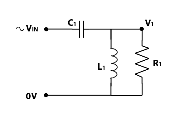
Thanks so much, Duke. I understand that this is the proper circuit:
When I go to your link, substituting 1k ohms instead of 8 ohms merely gives me the new values for the cap. and inductor. I can't see the overall impedance of the circuit.
When I go to your link, substituting 1k ohms instead of 8 ohms merely gives me the new values for the cap. and inductor. I can't see the overall impedance of the circuit.
- Nov 24, 2008
- 4,343
- 7,163
- Disclosures
- Owner & designer, AudioKinesis; Auth. mfg, Big E (Home Audio only)
Yup, that's what it looks like! R1 in the 5-8 ohm range would be a reasonable approximation of the driver's voice coil (we can ignore its inductance in this case), and a kilo-ohm ballpark value for R1 would approximate a blown voice coil or removal of the driver or other such open-circuit condition.
Unfortunately modeling or plotting the actual impedance curve is beyond any online calculator that I know of, but at least now you have a representative circuit as a starting point. I think the key to understanding the impedance dip is this statement by megafiddle:
My understanding is that we don't get the short circuit when we have the driver in the circuit because
That being said I do not have a formal background in electronics so I welcome correction from anyone who does (or who just knows more about this than I d0).
This virtual short-circuit should the tweeter fail is one of the things I take into account when I design a crossover. I don't want a blown tweeter (which might go unnoticed) to result in a blown amp (which someone is going to notice).
Unfortunately modeling or plotting the actual impedance curve is beyond any online calculator that I know of, but at least now you have a representative circuit as a starting point. I think the key to understanding the impedance dip is this statement by megafiddle:
An inductor and capacitor in series have zero reactance total at resonance...
My understanding is that we don't get the short circuit when we have the driver in the circuit because
As long as there is no effective series resistance in the circuit, the impedance is zero. If there is any resistance present, like coil resistance, or capacitor ESR, then the impedance will equal the resistance.
That being said I do not have a formal background in electronics so I welcome correction from anyone who does (or who just knows more about this than I d0).
This virtual short-circuit should the tweeter fail is one of the things I take into account when I design a crossover. I don't want a blown tweeter (which might go unnoticed) to result in a blown amp (which someone is going to notice).
Last edited:
Yup, that's what it looks like! R1 in the 5-8 ohm range would be a reasonable approximation of the driver's voice coil (we can ignore its inductance in this case), and a kilo-ohm ballpark value for R1 would approximate a blown voice coil or removal of the driver or other such open-circuit condition.
Unfortunately modeling or plotting the actual impedance curve is beyond any online calculator that I know of, but at least now you have a representative circuit as a starting point. I think the key to understanding the impedance dip is this statement by megafiddle:
My understanding is that we don't get the short circuit when we have the driver in the circuit because
That being said I do not have a formal background in electronics so I welcome correction from anyone who does (or who just knows more about this than I d0).
This virtual short-circuit should the tweeter fail is one of the things I take into account when I design a crossover. I don't want a blown tweeter (which might go unnoticed) to result in a blown amp (which someone is going to notice).
Yes, indeed-- got all that but, as we discussed via PM, it's difficult to understand, intuitively, how reducing the value of R1 in parallel with the inductor increases the impedance of the circuit. I know I'm missing something important.
If you're simulating in spice, add a little Series Resistance in the voltage source. It will plot.
There may be a simple way to see it.
When two impedances are combined in parallel, the lower impedance will predominate in the total value
of that combination. So a pure capacitance, in series with a pure inductance, will be zero impedance at
resonance. But if you place a 4 ohm resistor in parallel with the capacitor, the impedance of that circuit
section will be predominately resistive. The total impedance is now the inductive reactance in series with
the resistance.
-
When two impedances are combined in parallel, the lower impedance will predominate in the total value
of that combination. So a pure capacitance, in series with a pure inductance, will be zero impedance at
resonance. But if you place a 4 ohm resistor in parallel with the capacitor, the impedance of that circuit
section will be predominately resistive. The total impedance is now the inductive reactance in series with
the resistance.
-
Something that hasn't been mentioned: this dangerously low impedance only occurs at a specific frequency.
If that frequency is not present in the signal continuously, it isn't going to hurt anything.
-
If that frequency is not present in the signal continuously, it isn't going to hurt anything.
-
- Nov 24, 2008
- 4,343
- 7,163
- Disclosures
- Owner & designer, AudioKinesis; Auth. mfg, Big E (Home Audio only)
Something that hasn't been mentioned: this dangerously low impedance only occurs at a specific frequency.
If that frequency is not present in the signal continuously, it isn't going to hurt anything.
Agreed, so if it's fairly high up in frequency, it's probably not a problem for electric bass or plucked upright. I'm inclined to think bowed upright might be a different story, again it depends. For keyboards or PA, imo we'd want better amplifier protection.
One way of addressing the issue, from a crossover design standpoint anyway, is to add a resistor in series with the parallel inductor (assuming we're talking about a highpass filter). This will change the shape of the transfer function so other component values will probably have to change as well, and you might even have to go to a higher-order topology. Anyway my point is, there are techniques for building a high-order crossover such that the amplifier is adequately protected in the event of a blown voice coil.
There may be a simple way to see it.
When two impedances are combined in parallel, the lower impedance will predominate in the total value
of that combination. So a pure capacitance, in series with a pure inductance, will be zero impedance at
resonance. But if you place a 4 ohm resistor in parallel with the capacitor, the impedance of that circuit
section will be predominately resistive. The total impedance is now the inductive reactance in series with
the resistance.
-
...but the resistor is in parallel with the inductor. The fact that the lower impedance in a parallel arrangement predominates is precisely the issue. At resonance, why does hanging a resistance in parallel with the inductor raise the impedance? Earlier, you wrote:
If there is any resistance present, like coil resistance, or capacitor ESR, then the impedance
will equal the resistance. The equation is Z = square root ( (R squared) + (X inductive - X capacitive) squared) ).
So, now raise the series resistance to infinity (disconnected driver). Then, I believe, according to your equation, Z would equal infinity as well. If the impedance equals the resistance and the resistance is infinity, then must not the impedance equal infinity?
If there is any resistance present, like coil resistance, or capacitor ESR, then the impedance
will equal the resistance. The equation is Z = square root ( (R squared) + (X inductive - X capacitive) squared) ).
So, now raise the series resistance to infinity (disconnected driver). Then, I believe, according to your equation, Z would equal infinity as well. If the impedance equals the resistance and the resistance is infinity, then must not the impedance equal infinity?
Yes, that's correct. Sorry for the confusion.
The series resistance in that case is the resistance of the magnet wire used for the inductor,
and the effective series resistance of the capacitor. The resistance wasn't a separate resistor
component. I mentioned those resistances because a series capacitor and inductor may not
actually reach zero impedance if either of those resistances are present.
...but the resistor is in parallel with the inductor. The fact that the lower impedance in a parallel arrangement predominates is precisely the issue. At resonance, why does hanging a resistance in parallel with the inductor raise the impedance?
The effect is the same if the resistor is in parallel with the inductor. That part of the circuit is also
predominantly resistive. So now you have a resistor in series with a capacitor. I realize this doesn't
explain things too well.
At resonance, the separate impedances do not fall to zero. The inductor and capacitor may each
have a relatively high impedance. But because the reactances are opposite in phase, and equal at
resonance, they cancel; the capacitive reactance is subtracted from the inductive reactance. So the
total reactance is zero. When you add a resistor in parallel with the inductor, that part of the circuit
appears more like a resistor and less like an inductor. Most importantly, the phase in that section is
no longer opposite to the capacitor reactance phase. It no longer cancels.
The math also gets a little complicated. When a reactance is in series with a resistance, the formula
is simply "square root of the sum of the squares". It's relatively simple because reactance always has
a 90 or -90 degree phase, and resistance always has 0 degree phase. Once you combine a resistance
in parallel with a reactance, you get circuit element with some intermediate phase. Now you have to
use vector math to solve the equations. The "square root of the sum of the squares" is also a vector
addition; it is just special case where the phases are at 90 degrees.
This may help explain it:
Suppose you have an inductor and capacitor in series. The circuit is resonant, and each reactance is
50 ohms. The impedance is Xl - Xc which = 0 ohms. Now place zero ohms resistance in parallel with
the inductor. The circuit now consists of the capacitor alone. The inductor has been shorted out of the
circuit. What is the impedance?
-


