
Picked up a sunburst a few weeks ago. Made several upgrades, including the tuners, tone pot, knobs, string tree
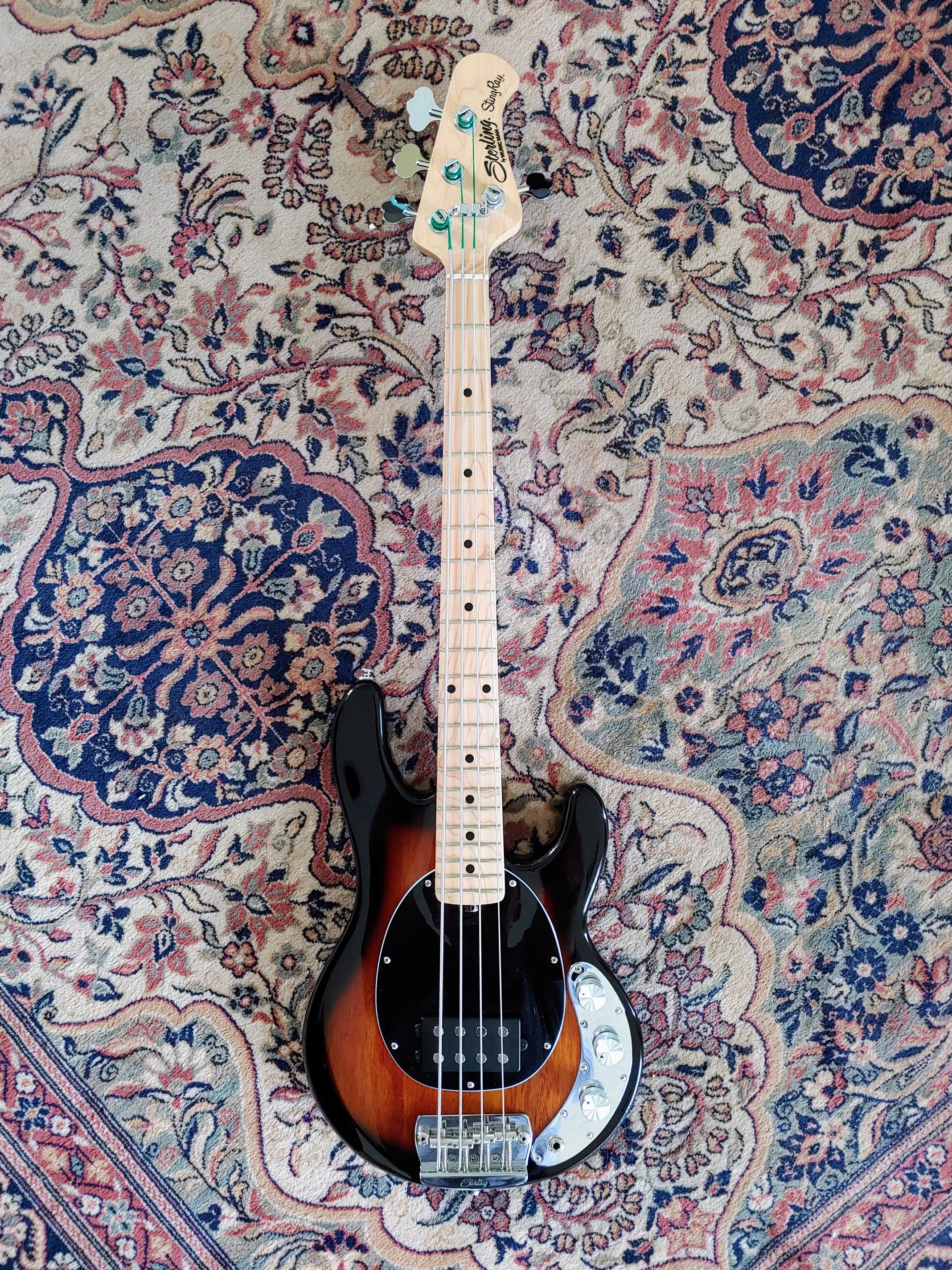
 and strings. Also hit the entire neck and fretboard with a Scotchbrite pad and wax. Very impressed with this little monster.

Enjoy the benefits of a premium membership!
Upgrade Account
-
TalkBass has been independent since 1998. Add your voice.
Create a free account to reply to discussions, view embedded media, and browse with fewer display ads.
Join free Log in
Want zero display ads or expanded classifieds tools? Compare plans.
You are using an out of date browser. It may not display this or other websites correctly.
You should upgrade or use an alternative browser.
You should upgrade or use an alternative browser.
SBMM Stingray Short scale
- Thread starter dralionux
- Start date
-
- Tags
- short scale bass
More options
Who Replied?

I like those knobs. Do you have a link? Thanks.Picked up a sunburst a few weeks ago. Made several upgrades, including the tuners, tone pot, knobs, string tree View attachment 4820565 View attachment 4820566 and strings. Also hit the entire neck and fretboard with a Scotchbrite pad and wax. Very impressed with this little monster.
AmazonI like those knobs. Do you have a link? Thanks.
https://a.co/d/fP0ZNVA
They are set screw type and fit on the 6 mm split pots. They are quite large (I like that size), and I also like that they have the indicator on the dial.
As an Amazon Associate, TalkBass may receive commissions from qualifying purchases made via links on this site.

Nice work and figure in the fretboard .Picked up a sunburst a few weeks ago. Made several upgrades, including the tuners, tone pot, knobs, string tree View attachment 4820565 View attachment 4820566 and strings. Also hit the entire neck and fretboard with a Scotchbrite pad and wax. Very impressed with this little monster.
It is really nice, overall. I'm very impressed with it for the price. I've heard that some people have had QC problems lately, but the one I got was pretty nice out of the box. 7 lbs, 12 oz. Stock. 7 lbs, 8 oz. after the mods.Nice work and figure in the fretboard .

Picked up a sunburst a few weeks ago. Made several upgrades, including the tuners, tone pot, knobs, string tree View attachment 4820565 View attachment 4820566 and strings. Also hit the entire neck and fretboard with a Scotchbrite pad and wax. Very impressed with this little monster.
Nice job on the tuners, they look factory.
These basses are absolutely wonderful, a great platform for upgrades, and fun as heck to play too.
Just an FYI for those looking to do mods to the pots. The tone pot that is stock in the bass is a 100k. So if you use a 500K or 250k pot in the bass, you will experience a brighter tone.
I purchased the EBMM stock tone pot for the USA version of this bass, which is 500k with 1/4 inch solid shaft. The holes in the control plate fit the larger USA pot, however, the sound is brighter as I said. I also purchased the USA Push Pull pot from EBMM but haven't installed it or examined the stock one yet. Just wanted bass brothers and sisters to be aware of this.
I purchased the EBMM stock tone pot for the USA version of this bass, which is 500k with 1/4 inch solid shaft. The holes in the control plate fit the larger USA pot, however, the sound is brighter as I said. I also purchased the USA Push Pull pot from EBMM but haven't installed it or examined the stock one yet. Just wanted bass brothers and sisters to be aware of this.
Just an FYI for those looking to do mods to the pots. The tone pot that is stock in the bass is a 100k. So if you use a 500K or 250k pot in the bass, you will experience a brighter tone.
I purchased the EBMM stock tone pot for the USA version of this bass, which is 500k with 1/4 inch solid shaft. The holes in the control plate fit the larger USA pot, however, the sound is brighter as I said. I also purchased the USA Push Pull pot from EBMM but haven't installed it or examined the stock one yet. Just wanted bass brothers and sisters to be aware of this.
I'm wondering, how are you going to incorporate the push pull pot? The SBMM pickup has a 3 way rotary switch (single coil, series, parallel) it seems you'd have to leave one of the pickup modes out.
I have a push/pull on the MMTW EMG that I installed in mine and it's just noiseless single coil and humbucking.
I don't think the EBMM model offers the same 3 way option as the SBMM does.
You can probably find a better quality 3-way switch at Mouser electronics online.
Actually, I was just going to replace the volume pot, which is push pull, and gives the volume boost in the pull position. I like having that feature for times when i need to stand out in a section.I'm wondering, how are you going to incorporate the push pull pot? The SBMM pickup has a 3 way rotary switch (single coil, series, parallel) it seems you'd have to leave one of the pickup modes out.
I have a push/pull on the MMTW EMG that I installed in mine and it's just noiseless single coil and humbucking.
I don't think the EBMM model offers the same 3 way option as the SBMM does.
You can probably find a better quality 3-way switch at Mouser electronics online.
The existing Alpha 3 way rotary seems to work fine. I will only replace that if it fails down the line.
Last edited:
Actually, I was just going to replace the volume pot, which is push pull, and gives the volume boost in the pull position. I like having that feature for times when i need to stand out in a section.
The existing Alpha 3 way rotary seems to work fine. I will only replace that if it fails down the line.
Oh right, I totally forgot about the volume boost and you're correct, that existing pot is pretty cheap.
It's actually not a volume boost it just removes a pad that is in the circuit which in turn makes the bass louder.
I wonder if there is any difference in the tone of the bass between the 2 volume modes.
I think if you change out the pot, you'll need to look at the old one for any resistors that they use to pad the volume, I don't think it's a function of the volume knob alone or the pickup itself.
One of the few mods I've done to mine so far is to replace the P/P volume pot with a quality standard pot.
The original simply gives full volume in the 'boost' position and a cut/pad in the 'normal' position.
Easy to achieve the same result by simply rolling back the volume with a standard pot (common practice with gittars), eliminating the rather cheap feeling P/P pot.
However, some folks are probably more comfortable using the pre-sets of a P/P....
The original simply gives full volume in the 'boost' position and a cut/pad in the 'normal' position.
Easy to achieve the same result by simply rolling back the volume with a standard pot (common practice with gittars), eliminating the rather cheap feeling P/P pot.
However, some folks are probably more comfortable using the pre-sets of a P/P....
Actually, I was just going to replace the volume pot, which is push pull, and gives the volume boost in the pull position.
The existing Alpha 3 way rotary seems to work fine. I will only replace that if it fails down the line.
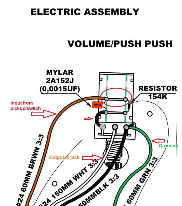
Here is a wiring schematic that someone posted earlier in this thread. There is a 156k resistor that is in series when the switch is pulled up. There is also a small capacitor that is in the circuit in both switch positions as it routs to ground. Not sure what the function of the capacitor is. The pot resistance is not provided on the diagram.Oh right, I totally forgot about the volume boost and you're correct, that existing pot is pretty cheap.
It's actually not a volume boost it just removes a pad that is in the circuit which in turn makes the bass louder.
I wonder if there is any difference in the tone of the bass between the 2 volume modes.
I think if you change out the pot, you'll need to look at the old one for any resistors that they use to pad the volume, I don't think it's a function of the volume knob alone or the pickup itself.
Attachments
That resistor is used for a common circuit called a "treble bleed" and is used to keep the treble from rolling off as you turn the volume pot down. G&L was the first company that I ever knew that used them, they work.Here is a wiring schematic that someone posted earlier in this thread. There is a 156k resistor that is in series when the switch is pulled up. There is also a small capacitor that is in the circuit in both switch positions as it routs to ground. Not sure what the function of the capacitor is. The pot resistance is not provided on the diagram.View attachment 4820823
And the cap is probably there to keep it from popping when you pull and push the switch.
Last edited:
I always like to learn new stuff. I read a great article about treble bleed circuits here:That resistor is used for a common circuit called a "treble bleed" and is used to keep the treble from rolling off as you turn the volume pot down. G&L was the first company that I ever knew that used them, they work.
And the cap is probably there to keep it from popping when you pull and push the switch.
Mod Garage: Deep Diving into Treble-Bleed Networks
So actually, the system shown in the schematic I posted, on the pull side of the volume switch is a treble bleed parallel circuit. What I'm NOT understanding, is how that system is boosting the volume. Anybody have an idea?
I always like to learn new stuff. I read a great article about treble bleed circuits here:
Mod Garage: Deep Diving into Treble-Bleed Networks
So actually, the system shown in the schematic I posted, on the pull side of the volume switch is a treble bleed parallel circuit. What I'm NOT understanding, is how that system is boosting the volume. Anybody have an idea?
As it´s a passive circuit it cannot "boost" - in one position it cuts the volume and the "boost" position is the normal volume/output level.

Which is super annoying. This bass is almost perfect as it is. Why did they didn’t just put an ordinary vol knob I’ll never understand. The push push control just seems gimmickyAs it´s a passive circuit it cannot "boost" - in one position it cuts the volume and the "boost" position is the normal volume/output level.
As it´s a passive circuit it cannot "boost" - in one position it cuts the volume and the "boost" position is the normal volume/output level.
That is my confusion related to the push pull pot. I always thought that when "pulled", the top 2 terminals were tied into the circuit, with the middle 2 terminals being the common. And when "pushed", the bottom two terminals tied into the circuit. By the explanation, the "pushed" position would tie in the resistor. So is this switch reversed compared to a normal push-pull?Treble bleed circuits have been around for a long time.. more common in the electric gittar world.
That schematic shows the volume hot output running thru the T/B in both positions, but shunting thru the resistor in the down position, thus reducing output.
I'd say you're right. I'm no wiring expert, but I have done many, many repairs & mods over the years.
The way I see this illustration, the switch is upside down. The top 2 contacts (in the red oval) show the signal path with the switch 'down' in a normal position. The 'hot' (pickup signal) passes thru both the T/B and the resistor on it's way to the short black wire that feeds the volume control to the output to the jack.
When the switch/knob is 'up', it only goes thru the T/B on it's way to the volume pot, giving full signal like a standard setup.
If I'm wrong about this, please educate me!
That being said, the stock setup sounds pretty good imho, but I prefer the simplicity of skipping the push/push...
The way I see this illustration, the switch is upside down. The top 2 contacts (in the red oval) show the signal path with the switch 'down' in a normal position. The 'hot' (pickup signal) passes thru both the T/B and the resistor on it's way to the short black wire that feeds the volume control to the output to the jack.
When the switch/knob is 'up', it only goes thru the T/B on it's way to the volume pot, giving full signal like a standard setup.
If I'm wrong about this, please educate me!
That being said, the stock setup sounds pretty good imho, but I prefer the simplicity of skipping the push/push...
Thank you! So, I'm not crazy after all...I'd say you're right. I'm no wiring expert, but I have done many, many repairs & mods over the years.
The way I see this illustration, the switch is upside down. The top 2 contacts (in the red oval) show the signal path with the switch 'down' in a normal position. The 'hot' (pickup signal) passes thru both the T/B and the resistor on it's way to the short black wire that feeds the volume control to the output to the jack.
When the switch/knob is 'up', it only goes thru the T/B on it's way to the volume pot, giving full signal like a standard setup.
If I'm wrong about this, please educate me!
That being said, the stock setup sounds pretty good imho, but I prefer the simplicity of skipping the push/push...
I opened the cavity and the resistor and cap are located on the top terminals, as shown in the diagram.
Last edited:


