
Enjoy the benefits of a premium membership!
Upgrade Account
-
TalkBass has been independent since 1998. Add your voice.
Create a free account to reply to discussions, view embedded media, and browse with fewer display ads.
Join free Log in
Want zero display ads or expanded classifieds tools? Compare plans.
You are using an out of date browser. It may not display this or other websites correctly.
You should upgrade or use an alternative browser.
You should upgrade or use an alternative browser.
schematic for SVT HD
- Thread starter Tony Gray
- Start date
More options
Who Replied?

RRJackson
Commercial User
I have a Skunkworks SVT HD and have had a hard short that left my VR4 Hum Control pot dead and the resistors attached to it blown apart. There's not even enough left of the resistors to identify their values. A schematic would be really helpful about now.
Here's a photo of the pot and the remains of the resistors that I removed:
http://www.flickr.com/photos/r_jackson/7789704872/
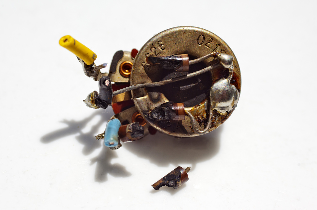
Here's a photo of the pot and the remains of the resistors that I removed:
http://www.flickr.com/photos/r_jackson/7789704872/

I don't have a schematic for you but your pic helps to figure out what was done.
Normally the Invalid Link Removed is 100 ohms, 5W wire wound. When it blows and the correct part is not available, sometimes an artificial center tap is used to replace the pot. It looks like this was done in your case.
You take two 100 ohm, 1/2 W resistors (brown, black, brown), tie one leg from each resistor together and connect that to ground, the other leg of each resistor is tied across each heater wire. See below. Looking at your pic I see two resistors tied together and connected to the center tap of the pot which goes to ground. The other ends of the resistors looks like they were tied to each outer tab of the pot where the heater wires are connected.
Artificial center tap
[Invalid or Expired Link Removed]
SVT heater schematic
[Invalid or Expired Link Removed]
With the resistors you are simulating the hum pot set in the center. This works because the hum is normally set very close to the center.
In a heater circuit you choose one of the following: a hum pot, an artificial center tap, or ground the center tap of the transformer heater winding (not all amps have one). You can't combine them. Most amps don't have hum pots. Often you see one of the other two options. The advantage of the artificial center tap is that the resistors act as a fuse and blow if there is a problem.
I would replace the hum pot and not use the two resistors.
Normally the Invalid Link Removed is 100 ohms, 5W wire wound. When it blows and the correct part is not available, sometimes an artificial center tap is used to replace the pot. It looks like this was done in your case.
You take two 100 ohm, 1/2 W resistors (brown, black, brown), tie one leg from each resistor together and connect that to ground, the other leg of each resistor is tied across each heater wire. See below. Looking at your pic I see two resistors tied together and connected to the center tap of the pot which goes to ground. The other ends of the resistors looks like they were tied to each outer tab of the pot where the heater wires are connected.
Artificial center tap
[Invalid or Expired Link Removed]
SVT heater schematic
[Invalid or Expired Link Removed]
With the resistors you are simulating the hum pot set in the center. This works because the hum is normally set very close to the center.
In a heater circuit you choose one of the following: a hum pot, an artificial center tap, or ground the center tap of the transformer heater winding (not all amps have one). You can't combine them. Most amps don't have hum pots. Often you see one of the other two options. The advantage of the artificial center tap is that the resistors act as a fuse and blow if there is a problem.
I would replace the hum pot and not use the two resistors.
RRJackson
Commercial User
Oh, man do I love an answer that works my brain enough so I have a better understand as to why I'm doing what I'm doing. Thank you. A lot. Thank you a lot.
-Rob
-Rob
I don't have a schematic for you but your pic helps to figure out what was done.
Normally the Invalid Link Removed is 100 ohms, 5W wire wound. When it blows and the correct part is not available, sometimes an artificial center tap is used to replace the pot. It looks like this was done in your case.
You take two 100 ohm, 1/2 W resistors (brown, black, brown), tie one leg from each resistor together and connect that to ground, the other leg of each resistor is tied across each heater wire. See below. Looking at your pic I see two resistors tied together and connected to the center tap of the pot which goes to ground. The other ends of the resistors looks like they were tied to each outer tab of the pot where the heater wires are connected.
Artificial center tap
[Invalid or Expired Link Removed]
SVT heater schematic
[Invalid or Expired Link Removed]
With the resistors you are simulating the hum pot set in the center. This works because the hum is normally set very close to the center.
In a heater circuit you choose one of the following: a hum pot, an artificial center tap, or ground the center tap of the transformer heater winding (not all amps have one). You can't combine them. Most amps don't have hum pots. Often you see one of the other two options. The advantage of the artificial center tap is that the resistors act as a fuse and blow if there is a problem.
I would replace the hum pot and not use the two resistors.
RRJackson
Commercial User
I would replace the hum pot and not use the two resistors.
BTW, and excuse me if this is a really stupid question, but I have adjusted my hum pot in the past. Any idea why I had a hum pot as well as a pair of resistors?
-Rob
You shouldn't have had both the hum pot and the resistors. You have one or the other. Otherwise you get what is called a ground loop and the hum that comes with it.
The inside of the pot is a curled resistive wire. It looks kind of like a curly instrument cable. The pot acts as a variable resistor, balancing one side of the heater circuit against the other to minimize noise in the circuit. I assume that your hum pot blew so someone added the resistors. This usually means that the curly wire melted and opened somewhere along its path. The pot wasn't working properly.
It is possible that between the wiper (center connector) and only one end of the pot the variable resistor was still working when you turned the shaft. This could account for any change in hum you heard as you adjusted it. Often an open pot like this causes even more hum.
Hope that this helps.
The inside of the pot is a curled resistive wire. It looks kind of like a curly instrument cable. The pot acts as a variable resistor, balancing one side of the heater circuit against the other to minimize noise in the circuit. I assume that your hum pot blew so someone added the resistors. This usually means that the curly wire melted and opened somewhere along its path. The pot wasn't working properly.
It is possible that between the wiper (center connector) and only one end of the pot the variable resistor was still working when you turned the shaft. This could account for any change in hum you heard as you adjusted it. Often an open pot like this causes even more hum.
Hope that this helps.
RRJackson
Commercial User
Very odd. Nobody but me has ever serviced that amp and I've never replaced that pot. So it obviously came like that from St. Louis Music since I'm the first and only owner of this amp. I think I have some photos taken of the guts of the amp some years back. I need to dig through them and see if I got a good shot of this.
-Rob
-Rob
You shouldn't have had both the hum pot and the resistors. You have one or the other. Otherwise you get what is called a ground loop and the hum that comes with it.
The inside of the pot is a curled resistive wire. It looks kind of like a curly instrument cable. The pot acts as a variable resistor, balancing one side of the heater circuit against the other to minimize noise in the circuit. I assume that your hum pot blew so someone added the resistors. This usually means that the curly wire melted and opened somewhere along its path. The pot wasn't working properly.
It is possible that between the wiper (center connector) and only one end of the pot the variable resistor was still working when you turned the shaft. This could account for any change in hum you heard as you adjusted it. Often an open pot like this causes even more hum.
Hope that this helps.
RRJackson
Commercial User
Unfortunately, it seems like I never got a shot of that area. I did all my shooting from the other side of the chassis.
I wish I'd been more thorough. You know, I think this amp may be the last of the SVT-HD chassis they built. It didn't come with a plaque telling what number of 500 it was, but there's writing inside that says the date and Dave Ryan's name and "500" next to it. Maybe they were down to the bottom of the cupboard on parts and the last pot wasn't any good. I mean, I adjusted it before and thought I was accomplishing something, but I very well may have been making "improvements" that only a hamster on a wheel in my brain was convinced meant anything.
This is one of the shots I took a while back:
http://www.flickr.com/photos/r_jackson/5648115916/

I wish I'd been more thorough. You know, I think this amp may be the last of the SVT-HD chassis they built. It didn't come with a plaque telling what number of 500 it was, but there's writing inside that says the date and Dave Ryan's name and "500" next to it. Maybe they were down to the bottom of the cupboard on parts and the last pot wasn't any good. I mean, I adjusted it before and thought I was accomplishing something, but I very well may have been making "improvements" that only a hamster on a wheel in my brain was convinced meant anything.
This is one of the shots I took a while back:
http://www.flickr.com/photos/r_jackson/5648115916/
RRJackson
Commercial User
Interesting.... Should also have a plaque.
I do have SVT-HD info, but they are very large files, with a bunch of semi-confusing stuff in them. But I can send, probably in several sections.....
I do have SVT-HD info, but they are very large files, with a bunch of semi-confusing stuff in them. But I can send, probably in several sections.....
Unfortunately, it seems like I never got a shot of that area. I wish I'd been more thorough.
I know what you mean. I do that all the time. The one shot that you need is often the one that you didn't take.


I also have been looking for an HD schematic since I got mine. I just used the SVT schematic that I did find and was pretty lucky that replacing the super caps fixed the problem. Now I've got the best bass head on the block, #391/500.
RRJackson
Commercial User
Interesting.... Should also have a plaque.
I do have SVT-HD info, but they are very large files, with a bunch of semi-confusing stuff in them. But I can send, probably in several sections.....
I would love to see the info you have, if at all possible. I assume my email address is visible to you. Please feel free to email me anything. I think my limit is 20 meg per item.
-Rob
RRJackson
Commercial User


