• TalkBass has been independent since 1998. Add your voice.
    Create a free account to reply to discussions, view embedded media, and browse with fewer display ads.
    Join freeLog in
    Want zero display ads or expanded classifieds tools? Compare plans.

Template And Fixture Set For A New Design EUB Neck

Bruce Johnson

Gold Supporting Member
Commercial User
Feb 4, 2011
16,067
56,987
70
Fillmore, CA
www.xstrange.com
Disclosures
Professional Luthier
Hello everyone;

I've got a new R & D project going on here. I'm developing a new model of an Electric Upright Bass, from scratch, which I intend to build in production over the coming years. I'm doing this project working with a good friend of mine, Juan Perez, He came to me with the overall idea and design concept. I'm doing the R & D and engineering and tooling. The plan is that I'll be building these basses in batches and providing them to him in kit form. He'll be doing the finishing and assembly, and all of the marketing and sales and dealing with customers.

On here, I'm not going to talk too much about the design or features of the bass, or its value in the marketplace. That's another topic for another time and place. This thread is about the process of developing all the tooling, templates and fixtures for building the necks. I'm going to be building them almost completely with my Pin Routers, which you've probably seen in my thread about Pin Routers. And I plan to build them in batches of 5-10 at a time.

There is a process to developing a set of templates and fixtures, and that's what I'm showing here. And, by the way, this is all being done with no computers or CAD or CNC. Old School pencil layouts right on the MDF! I'm hoping that this will be useful to some of you in your projects.

We're developing two versions of this bass. The Pulga (Spanish for "Flea") is 35" scale, very portable. The Moscha ("Fly") is full size 41" scale. I'm doing the tooling for both of these necks at the same time. They have the same headstock, but different lengths and fingerboard dimensions.

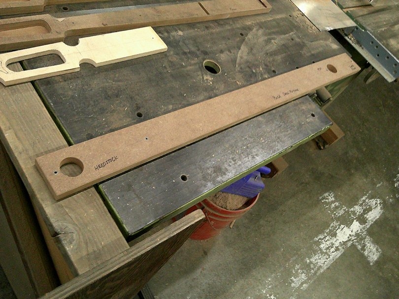
Here are the basic templates:
DSCF0869.JPG


First, and most important, is the Master Drill Guide. It's a rectangular strip of MDF with four steel Drill Guide bushings pressed in. They are for a #30 size drill, which is a tiny bit over 1/8". I use 1/8" steel dowel pins to accurately locate everything during the whole production process. The Drill Guide is used to drill all the reference holes in all of the other templates and fixtures, and all the reference holes in every production neck. Everything fits together accurately, because they all come back to this one Drill Guide.
DSCF0870.JPG


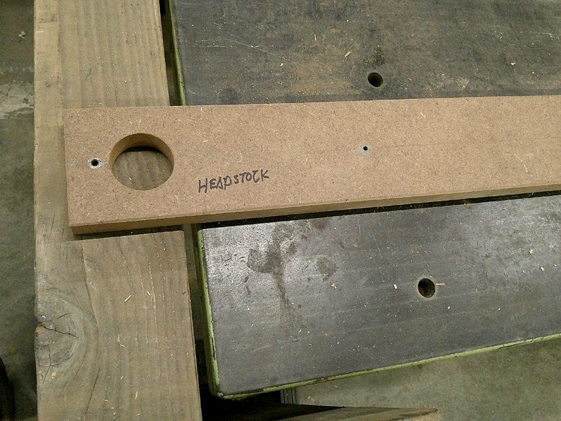
At the headstock end of the Drill Guide, there's one bushing for the reference hole out on the tip of the headstock. The second bushing is for the pin to locate the outboard end of the fingerboard. These two holes are the same on both model necks.
DSCF0871.JPG


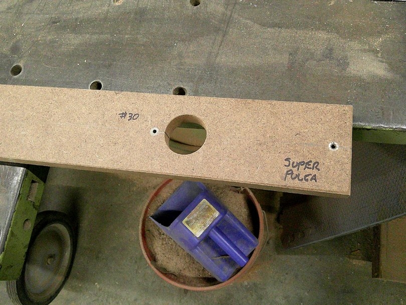
At the heel end of the Drill Guide, the two bushings are for the heel ends of the two different length necks. The same holes also locate the heel ends of the fingerboards.
DSCF0873.JPG


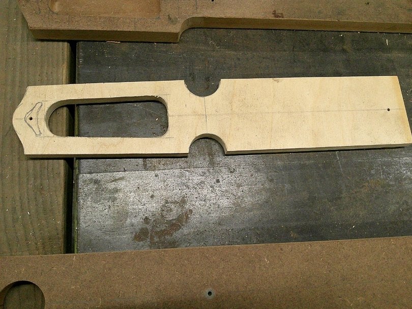
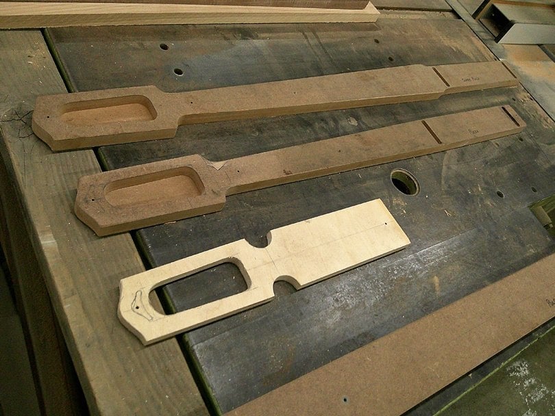
Next up is the Headstock Master Template. This is made from 1/2" Baltic Birch plywood. This is the sketchpad where I designed the headstock. I drew it out in pencil, full size, right on the plywood. Figured out the positions of the tuners, all the angles and contours. Then I went at it with Forstner bits, scroll saw, spindle sander and files. Took my time to get it perfect.
DSCF0872.JPG


Next up are the two main Routing Templates, one for each neck. They started out as straight strips of 3/4" MDF, and I did my initial pencil layouts of the whole neck on them. That's how I established the locations of the reference holes in the Drill Guide. In pencil. Then, after I made the Drill Guide, I used it to drill the actual reference holes in the Routing Templates.

That's the general theme here. I use these templates back and forth to make each other. To make sure that they all accurately line up with each other.
DSCF0874.JPG


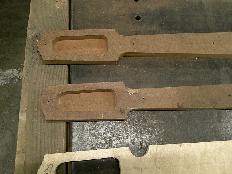
The headstocks are the same on the two necks, so I used the Master Headstock Template in the pin router to make exact copies on the two Routing Templates. That's what pin routers are so good at. I'll show how I did that a little farther down.

And yes, that's a patch on the Pulga Routing Template. When trimming it up, I screwed up on the spindle sander and cut that blend radius too deep. So, I bandsawed that V-notch and glued in a scrap of MDF, then re-cut it. That's one reason that MDF is great for templates: It's easy to repair and modify.
DSCF0875.JPG


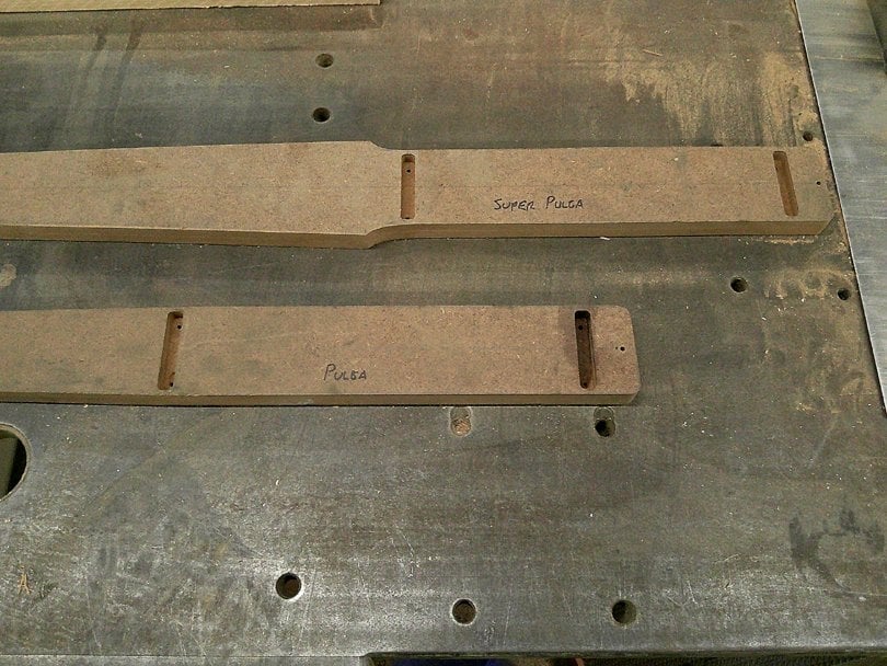
At the heel end of the Routing Templates are the slots for the Neck Bars. Same general idea as my legendary BruceBars, but going cross-wise. I cut the slots in my milling machine, while the templates were still rectangular strips.
 
Loving this thread already ! I am 100% sure I’ll be learning some new things that I can adapt into my workflow and increase efficiency (and quality) !

Yes, templates and fixtures like this are very useful, even if you are only making one instrument for yourself. Do all the thinking, engineering and precision cutting on the templates. Use them to check the fit, feel and look before you start cutting the real wood. If you find mistakes, or change your mind, fix the template with patches or more trimming. Or set it aside and start another one. When it's just right, then use a router to copy it in the real wood.

And the same goes for the fixtures, which you'll see coming up. Pre-test them on some scrap wood, and adjust them if needed, before cutting the real wood.

Craftsmanship is finding your mistakes before they happen, and fixing them before anyone knows.
 
Last edited:
I'm going to be jumping around a bit in this thread, because that's what I was actually doing! I'm moving back and forth between different templates and fixtures and special tools, using them to calibrate each other.

Backing up to the Headstock Master Template:

DSCF0802.JPG


Here's the Engineering Layout, on the plywood blank. Pencil and machinist's rulers and a drafting circle guide template. Old School Engineering. In the background, you can see the MDF blanks for the two Routing Templates, with the basic pencil layouts of the whole neck. And they both have the Reference Holes drilled by the Drill Guide.

DSCF0803.JPG


Here's the Headstock Master Template, all carefully trimmed out to the pencil lines. Hogged out the inside with Forstner bits, rough cut with the scroll saw, bandsawed the outside, spindle sander and edge sander to get real close to the lines, then careful hand filing to make it all straight and true. This template also has the reference hole up on the tip of the headstock.

DSCF0804.JPG


To transfer the headstock shape to the two Routing Templates, I pin the headstock template down to the blank. And I taped a piece of matching 1/2" plywood on there to support it and keep it from tipping.

DSCF0805.JPG


Then this goes face-down into the MGPR (Medium Green Pin Router) to copy the shape. Using one template to make the next template. Accurately.

This could also be done with a hand router and a bearing bit, flipped over with the plywood template on top.

DSCF0806.JPG


And there's the headstock shape routed into the Pulga template. Repeat for the other one.
 
I might add, for those who are new to template making ….

When you get your template(s) perfect, IMMEDIATELY use it to make a second one… a “Master” template. That way if/when you damage a template, you can quickly make another one from the Master.

Sorry for the interruption…. :)

Actually, I do it the other way around.....The first template that I make by hand is the Master. I get it accurate and perfect. Then I use the Master to make the Routing Template. That's the one that does the work making parts. It gets the wear and abuse. The Master gets stored in the cabinet and only gets used to repair or remake the Routing Template. The Master Template is effectively the engineering drawing, stored away for future use.
 
Actually, I do it the other way around.....The first template that I make by hand is the Master. I get it accurate and perfect. Then I use the Master to make the Routing Template. That's the one that does the work making parts. It gets the wear and abuse. The Master gets stored in the cabinet and only gets used to repair or remake the Routing Template. The Master Template is effectively the engineering drawing, stored away for future use.

Either way definitely works …. As long as you make the duplicate immediately, that way it’s perfect. :)
 
  • Like
Reactions: JIO and Beej
Next in the set of templates are the two Fingerboard Templates. On these necks, I decided to cut out the blanks for the fingerboards, and use a fixture to rout the sides of the fingerboards to the final width, while they are a separate part. Then they get glued to the neck using dowels in two of the reference holes. Meanwhile, the sides of the neck will have also been routed to the final width. So, the side surfaces of the fingerboard and the neck need to match exactly.

DSCF0876.JPG


Here are the two Fingerboard Templates, to match with the two Routing Templates for the two different size necks. They are made from 3/4" MDF.

DSCF0877.JPG


Each Fingerboard Template has two steel drill guide bushings pressed in. They are located using the main Drill Guide. So, they line up with the holes in the neck.

In production, the Fingerboard Template does several jobs. First it acts as a drill guide, and a Tracer. I lay the template on the bare board and align it visually to get the grain where I want it. Then clamp it down and drill the two reference holes through the drill guide bushings in the Template. In the back side of the fingerboard, and not all the way through, obviously. Then I pin the template to the board, through the reference holes, and draw all around the outside with a pencil. Pull off the Template, and bandsaw out the fingerboard blank, outside the pencil lines.....

The side surfaces of the fingerboard will get routed with a special fixture........

DSCF0812.JPG


So, here it is......This is what I call a T-style Flip-Over fixture. It's simple construction, made from 3/4" MDF. The base is 6" wide, and the center board is 4" high. The fingerboard blank mounts on the side of the center board, plugging onto two dowel pins and clamped. The rounded notches are for the clamps.

After sliding it through the pin router and cutting one side of the fingerboard, the fingerboard is unclamped and flipped over and clamped on the back side of the center board. The same dowel pins go all the way through the center board and stick out the back. Another pass through the pin router to cut the other side straight and true.

And the Flip-Over thing makes sure that it's symmetrical.

DSCF0813.JPG


The underside of the fixture base has four slots, two pairs, cut with the tablesaw. These guide on the pin of the pin router.

DSCF0814.JPG


Here's how a fingerboard blank will mount on the fixture. Two pins and two clamps.

But this is one of the Fingerboard Templates, still bandsawn oversize at this point. While I'm making calibration passes on the fixture, I'm also cutting the final side surface of the Template. Making sure they exactly match. Then it'll get flipped over to cut the other side.


DSCF0816.JPG


In action in the MGPR. This a router planing type operation, cutting with the face of the router bit. One pass, sliding down one slot and back the other. Climb cutting in both directions, so it won't tend to splinter out the surfaces.

You could do this same operation with a hand router. Same style fixture, just add the two parallel side rails for the router base to ride on.

DSCF0817.JPG


There's the completed fixture, and the two finished Fingerboard Templates.

Note that the top edge of the center board of the fixture was also cut flush at the same time as I was cutting the templates. So, that center board now serves as the setting gauge. Any time I'm setting up to use this fixture. I adjust the router bit down (while shut off!!!) until it just touches that center board. That's the correct height to make the cuts.

DSCF0818.JPG


And now, I plug the two Routing Templates onto this same fixture, same setup, to cut their final side surfaces. To make sure the necks match the fingerboards. And Templates match Templates.
 
Last edited:
Very nice ! That gives me some ideas. I’m getting to make some separate fretboard templates. I’ve always just made a single neck template that had the fretboard included, but I think going to start doing two part templates :

Neck template that has the headstock shape, holes to mark tuner locations, referencing pin hole locations, and a truss rod template down the center. Also locations for neck bolts/ or Bruce bar templates.

Fretboard template that has referencing pin locations and (perhaps) has dot inlay locations for the board. Still deciding on whether to include the dot inlay locations.

I really like the flip up idea of yours. I want to read it a bit more in depth and see how it will work for my needs.

I think making these as matched sets, though it will take extra time initially, will pay off in “time saved” and “accuracy”. I definitely want to make everything as easy and streamlined as possible.


Question for you, @Bruce - on your templates, do you reinforce the edges (with superglue, or wipe on poly, or epoxy) ? I’ve done it both ways, and I think I’ll be brushing some wipe on poly just to help extend the life of the templates.
 
Question for you, @Bruce - on your templates, do you reinforce the edges (with superglue, or wipe on poly, or epoxy) ? I’ve done it both ways, and I think I’ll be brushing some wipe on poly just to help extend the life of the templates.

I normally don't need to do any reinforcement of the edges of the MDF on my templates and fixtures. If I do see a spot of some wear or damage, then I'll dab on some West Systems and sand it smooth.

If you live somewhere with higher humidity and rainfall, then it's a good idea to coat your MDF tooling with polyurethane, to seal up the edges and keep them from soaking in moisture and swelling.
 
Moving on with developing the manufacturing process: Preparing the neck blanks.

We're building these Pulga and Moscha basses all from 4/4 cherry; necks, fingerboards and bodies.

DSCF0828.JPG


Here are the strip sets of cherry for the prototype Pulga and Moscha necks. Three piece laminate down the length of the neck, plus two extra caps on the sides of the headstock. Ripped on the tablesaw, right from a 4/4 cherry board. Real simple.

Note: Now that these two prototype necks are nearing completion, I'm not real happy with where the glue seam lines are appearing on the back of the neck, in relation to the shape. I may be changing the lamination buildup to 4 strips down the full length, without the headstock caps. That's what prototypes are for, to find things that can be improved.

DSCF0830.JPG


The laminations are glued up with West Systems epoxy, on waxed paper, on my neck gluing beams, with my trusty clamps. No special tooling needed here.

DSCF0837.JPG


And there's the two prototype cherry blanks, glued up. I also made one in walnut, from a leftover board that I had here.

DSCF0838.JPG


Here's where the Master Drill Guide comes in. I measure and draw a centerline on the center strip of the lamination, at the headstock end, and drill a #30 hole. I pin the Drill Guide to that hole and.......

DSCF0839.JPG


.....at the other end, I line up the Drill Guide with the centerline. That's what the big hole in the Drill Guide is for; so I can see the line. Then drill the rear hole down through the drill guide. The two Reference Holes go all the way through the neck blank, headstock and heel.

DSCF0791.JPG


Next up is router planing the front and back surfaces of the neck blank, using the SPRP! And this calls for a special fixture! Simple construction: two slabs of MDF. The bottom slab happens to be veneer faced MDF, a leftover given to me by my buddy Eric, who is a cabinet maker with his shop down the hall.

DSCF0790.JPG


As with my other SPRP fixtures, the bottom side has four long slots, cut on the tablesaw, with V-notches at the front.

DSCF0792.JPG


The neck blank plugs down onto two steel dowel pins. T-nuts at the back corners for two of my fixture handles to screw in.....

DSCF0793.JPG


And there it is in operation, router-planing the top surface of the blank in the SPRP.

DSCF0794.JPG


If you haven't seen it before, the SPRP (Super Pin Router Planer, pronounced SPiRP) is a special machine that I developed and built a few years ago. It's a Pin Router made to do router planing, cutting accurate flat surfaces on instrument necks and bodies. It works very well.

If you want to read more about this machine (and maybe build one for yourself) the story starts on the Router Planing thread, where I built the SRP (Super Router Planer). It then evolved into the SPRP, and moved over to the Pin Routers thread.

DSCF0795.JPG


Here's what it does. This is actually the walnut neck. After cutting the top surface flat and true, I flip the blank over in the fixture, plug it back onto the two dowel pins, and cut the back surface. Down to the final thickness.
 
Next up: the tuner holes

In the production sequence, I want to drill the holes for the tuners in the sides of the headstock before routing the inner and outer walls of the headstock. This prevents splintering out of the holes on the inside wall, which can easily happen if the holes are drilled after routing the wall surface. I learned this from my years of Scroll Bass headstocks.

So, how to drill the holes quickly and accurately in the uncut headstock blank, in production?

DSCF0807.JPG


Yep, you guessed it, this calls for a special Drill Fixture! Simple construction, T-style, Flip-Over design, MDF strips. The neck blank plugs onto two dowel pins on one side. Two holes are drilled down through an aluminum drill guide plate, to a particular depth. Then the blank is flipped over to the opposite side, onto the other end of the same dowel pins, to drill the other two.

DSCF0808.JPG


The drill guide is a piece of 1/4" 6061 aluminum plate. I laid it out accurately and drilled the holes 35/64", with the same drill bit that I'll be using to drill the necks. I bought the bit specifically for this job, and will keep it dedicated for this purpose. The plate is carefully lined up on the fixture, and held on with two dowel pins and one screw.

DSCF0809.JPG


I do the drilling in my big old Royersford drill press, slow spindle speed.

DSCF0810.JPG


DSCF0811.JPG


And there's the holes! With the fixture, it's maybe 2 minutes per neck. And they are accurately in place.

Another operation down; more to go......
 
Last edited:
Next operation: Routing the plan view shape of the neck. This includes the perimeter around the outside of the neck, the inside of the headstock, and the slots for the heel bars.

Two new fixtures, one for each of the size necks:

DSCF0821.JPG


Simple fixture construction; a long strip of MDF. This is some more of that veneer-faced MDF that Eric gave me. This is the underside of the fixture. the Routing Template (made previously) is mounted on the two dowel pins. The same pins extend through and stick out the top, for the neck blanks to pin onto. Three 1/4-20 T-nuts for the screw-in rubber handles. And a 1" wide strip of MDF is screwed along the edge for stability, so the fixture stays flat and slides on the pin router's table.

DSCF0822.JPG


Here's the pair of fixtures, for the long scale Moscha neck and the compact Pulga neck.

DSCF0820.JPG


The first test job for these fixtures is to make up a pair of Tracer Templates. These are made from some thin plywood, routed to the final outside shape and dimensions of the neck. Here, the Pulga tracer template is rough bandsawn to slightly oversize and is pinned to the routing fixture.

DSCF0819.JPG


Here's the router fixture in use in the MGPR, routing the perimeter of the Moscha Tracing Template. The usual process: a 1/4" router bit with a 1/4" pin in the table, sliding the fixture around, holding it by the handles, with the pin riding around the the routing template on the underside of the fixture.

DSCF0878.JPG


And there's the two Tracing Templates with their matched Routing Templates.

DSCF0823.JPG


And this is what the Tracing Template is for: I plug it onto the neck blank, with pins into the two reference holes, then draw around the outside of it with a pencil. For this walnut blank, I use a white pencil.

DSCF0824.JPG


And then bandsawed off the excess, staying outside the white line.

DSCF0825.JPG


And here we go with the first test run! The walnut neck blank is pinned down to the fixture, and the handles are attached. This is the setup in the MGPR: 1/4" router bit and 1/4" pin.

I routed the bar slots first, in three passes, to a depth of 3/8". Then I routed the inside of the headstock, all the way through, in 6 passes of 1/8". Then all around the perimeter, down the sides and around the headstock and heel.


DSCF0826.JPG


Here's the headstock after routing. It came out nice and smooth, no real problems with tearout.

But I later discovered that the headstock sides were slightly asymmetrical by about 1/16", which was causing problems in some of the upcoming operations. So, I went back and corrected the Master Headstock Template, and used it to correct the two Routing Templates. Then used these fixtures to correct the three prototype necks.

DSCF0827.JPG


In case you were wondering, those round Forstner bit holes under the corners of the neck are used like this, with a small pry bar, to gently lift the neck up off the dowel pins without damaging the edges.

That maple block screwed down in the foreground is a setting gauge for pre-setting the depth of the bar slots. But I found that it really isn't necessary, and removed it.

DSCF0841.JPG


Also, on the walnut neck, I cleared out the inside of the headstock completely by routing. That got a little tedious. So I went back and routed the headstock openings in the two Tracer Templates. Then when doing the operation on the two prototype cherry necks, I also traced the inside of the headstock. And pre-hogged out most of the wood with a 1" Forstner bit. It saved time.

DSCF0879.JPG


DSCF0880.JPG


And there are the two cherry necks with their perimeters all routed. I think this operation is all dialed-in for production.
 
Next step: Routing small flat pads on the sides of the headstock for the tuners to seat.

DSCF0849.JPG


Here's what I need to do: Because the sides of the headstock are angled, I need to rout small pad surfaces which are square to the tuner holes, for the tuner bases to seat against.

DSCF0850.JPG


Like this. Barely visible, but necessary.

DSCF0845.JPG


I started out by cutting an opening in a piece of 1/8" aluminum plate, drilling and hand filing. A nice fit with clearance around a tuner base. Then I laid out the tuner positions on a block of MDF, and screwed the aluminum plate down on one of the positions....

DSCF0843.JPG


I flipped it over, so the aluminum plate is on the bottom, and set it up in the MGPR. I used a 3/16" bit and pin to rout the openings, one at a time. Then move the aluminum plate to the next opening position and repeat. The large aluminum plate in the foreground is there to support the front edge of the MDF block, and keep it from tipping.

DSCF0844.JPG


And there's the Routing Template for the Tuner Pads.

DSCF0847.JPG


To do the routing, I need to hold the neck up on its side and do the Flip-Over thing. Rather than build another whole fixture, I just added this function to the previous Tuner Hole Drill Fixture. An extra set of dowel pin holes, mounting the neck with the headstock in the center.....

DSCF0846.JPG


...And sawing a chunk out of the bottom base, to mount the routing template. A Dual Function Fixture!

DSCF0848.JPG


Testing the operation on the Walnut neck, in the MGPR. Same setup; 3/16" bit, 3/16" pin. It basically worked well, but I noticed a little problem with the fixture wobbling fore/back slightly as I slid it around.....Which was messing with the accuracy of the routed pad......

DSCF0855.JPG


So, changed the front base plate on the fixture to this one, 9" wide......

DSCF0856.JPG


Now it doesn't wobble.

DSCF0851.JPG


Doing the operation on one of the cherry necks....Very quick, maybe 3 minutes for all four pads.

DSCF0853.JPG


All good, ready for production!
 
Last edited:
The next problem to be solved: Counterbores for the tuner bushing washers.

DSCF0860.JPG


Here's the problem: When I fit the tuner into the side wall of the headstock, the nut flange and washer of the bushing will contact the angled wall. That ain't right! I need to cut a small counterbore recess that's perpendicular to the hole. How do I do that on the inside wall of the headstock?

DSCF0868.JPG


This calls for.......A special tool! I quickly machined up this custom Reverse Counterbore and its Turning Key. Not really difficult; it took me about an hour to make. The cutter is machined from 304 stainless in the lathe, then the teeth are cut in the milling machine with a spin index fixture. Then the back clearance of the teeth is hand filed. The Key is bandsawn and filed from a chunk of aluminum, with a 1/8" steel dowel pin pressed in.

DSCF0861.JPG


The cutter has four teeth, shaped to cut in the downward direction.

DSCF0862.JPG


Here's the shape of the teeth; the sharp edge at the bottom, with the back clearance filed on the bottom.

DSCF0863.JPG


In use: I slip the cutter into the tuner hole from the inside.......

DSCF0864.JPG


Hook the Key into it, then pull gently outward while hand turning it 5 or 6 half turns.

DSCF0866.JPG


And there's the counterbore, nice and neat. It took about 30 seconds each.

Another operation checked off the list.
 
In the machine shop world, there are cutters available called a Back Spot Facer. It's a long shank with a pilot diameter, and a larger flange head on the end. The head has cutting teeth on the inner side. They are typically used in a milling machine to make a Spot Face (counterbore) on the back side of a hole that you've just drilled/bored. It allows you to do the operation right there, while the spindle is already aligned with the hole. Insert the Back Spot Facer through the hole from the back side and chuck it in the spindle. Make the cut by pulling back on the spindle.

That's where the basic idea came from for my special tool.
 
In the machine shop world, there are cutters available called a Back Spot Facer. It's a long shank with a pilot diameter, and a larger flange head on the end. The head has cutting teeth on the inner side. They are typically used in a milling machine to make a Spot Face (counterbore) on the back side of a hole that you've just drilled/bored. It allows you to do the operation right there, while the spindle is already aligned with the hole. Insert the Back Spot Facer through the hole from the back side and chuck it in the spindle. Make the cut by pulling back on the spindle.

That's where the basic idea came from for my special tool.


Thank you for the explanation, now I have more fun things to research !!!

I’m a knowledge junkie… I get interesting something and I go into “deep dive” mode ! 😂