• TalkBass has been independent since 1998. Add your voice.
    Create a free account to reply to discussions, view embedded media, and browse with fewer display ads.
    Join freeLog in
    Want zero display ads or expanded classifieds tools? Compare plans.

Template And Fixture Set For A New Design EUB Neck

Continuing on with the problem solving on the Pulga necks:

Adding some beautification to the headstocks:
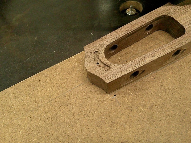
DSCF0885.JPG


I'm putting an emblem on to the top of the headstock. The emblem itself is going to be cast from transparent red epoxy, and look like a faceted ruby. I need to rout a little recess for the emblem to be set into. I made up a quick fixture and routed the recesses in the three prototype necks.....
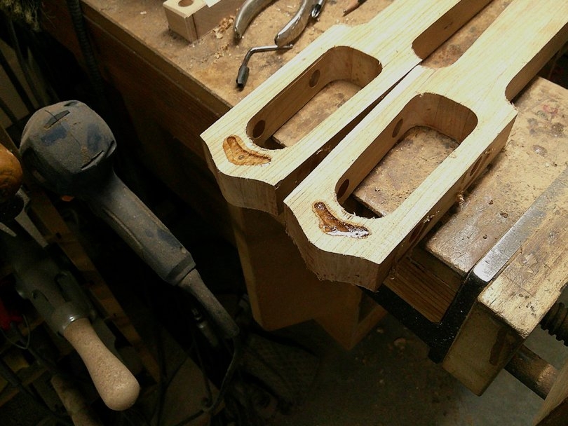
DSCF0886.JPG


They came out okay, but.....The shape and position wasn't quite right. So, I filled the recesses in the necks with epoxy, and started over.....
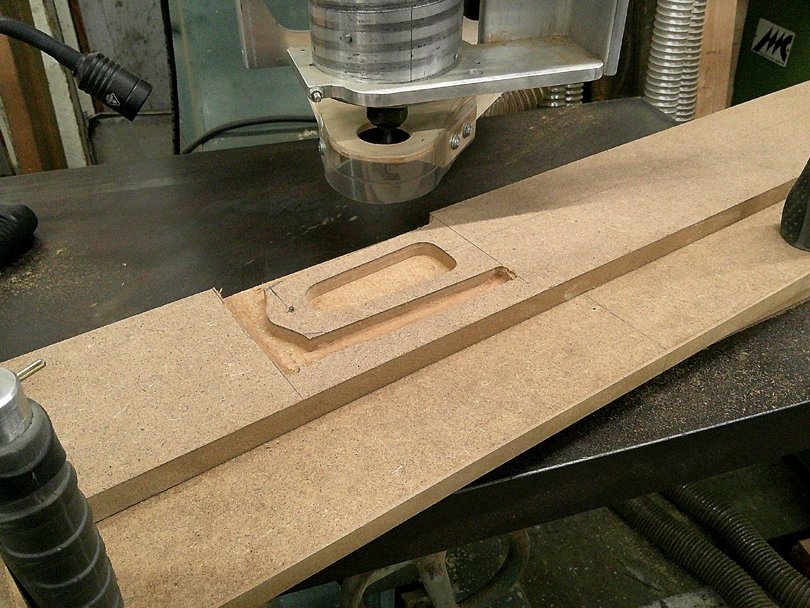
DSCF0887.JPG


So, I went ahead and built up the next fixture, which will do the beading cuts around the edges of the headstock. On this routing template, the headstock perimeter and inside shape are copied from the main routing template. This will guide the beading bit.
DSCF0889.JPG


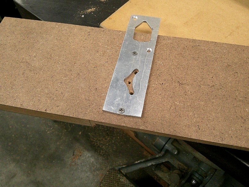
Then I made up a good aluminum Master for the shape of the emblem inlay, and accurately located it on the back side of the template....
DSCF0888.JPG


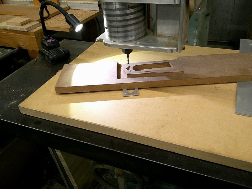
And used the pin router to copy the recess onto the working side of the routing template.......
DSCF0890.JPG


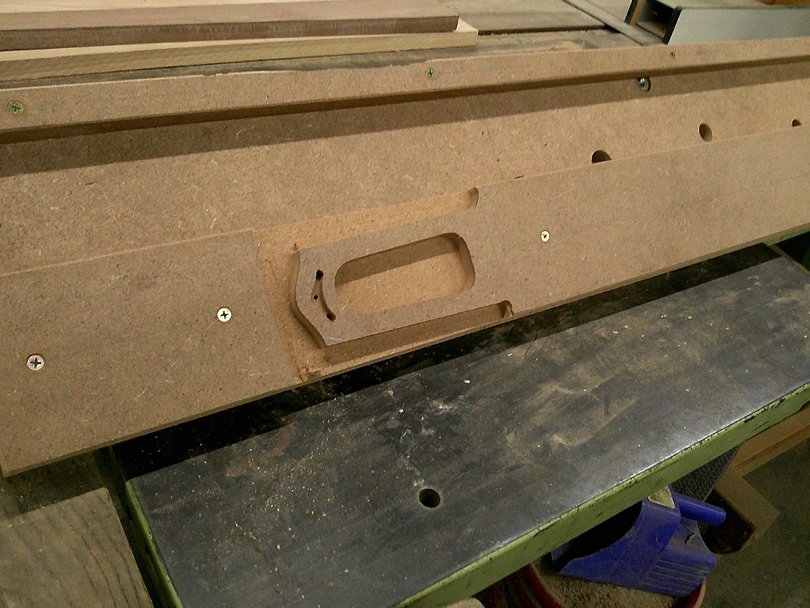
There's the finished routing template for doing the two headstock operations: the emblem recess, and the beading.
DSCF0891.JPG


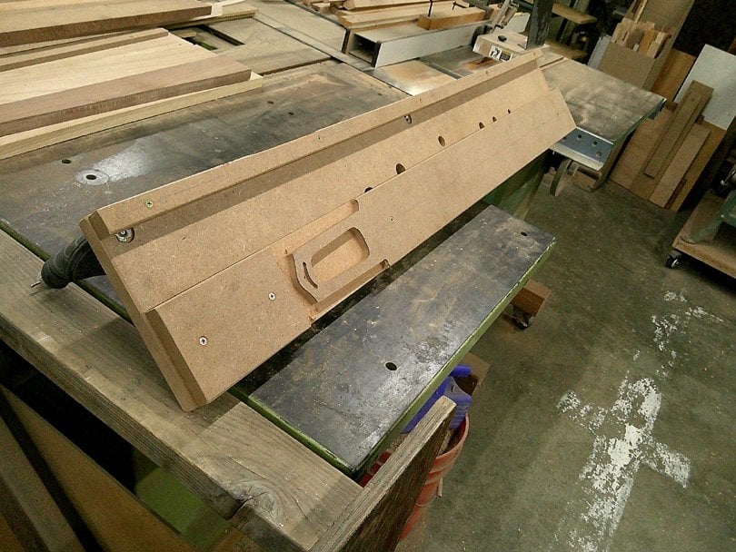
And there's its own dedicated fixture. Same design as the previous fixtures; a long MDF board with the MDF sliding strip.
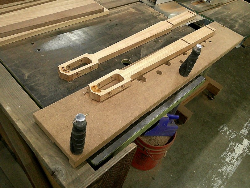
DSCF0892.JPG


Both size necks fit on this fixture. Just two handle positions, because I'm only working the headstock area.
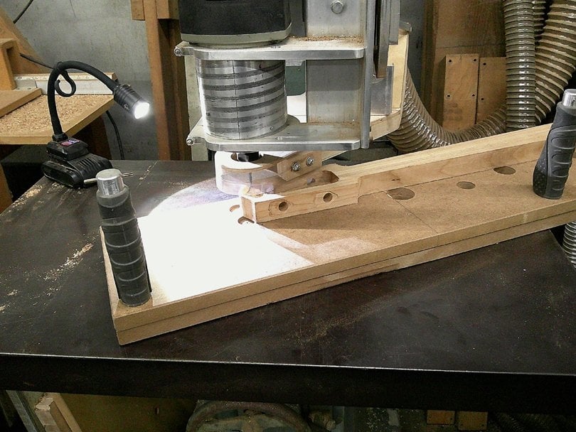
DSCF0894.JPG


Routing the inlay recess, using a 3/16" bit and 3/16" pin.
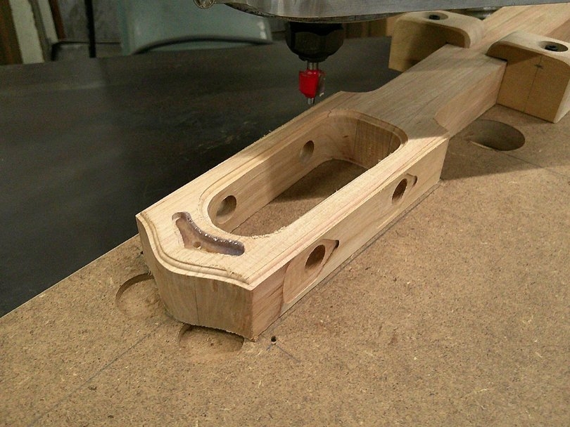
DSCF0911.JPG


Cutting the beading using a Freud 1/16" Beading Bit. I've removed the bearing, because the bit is now guided by the pin on the template underneath.

After cutting the beading on the top, I flip the neck over in the fixture and do the same cut on the back side of the headstock...
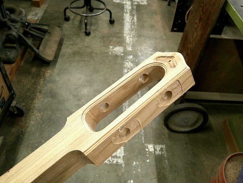
DSCF0915.JPG


Here's what the beading looks like, on the front side......
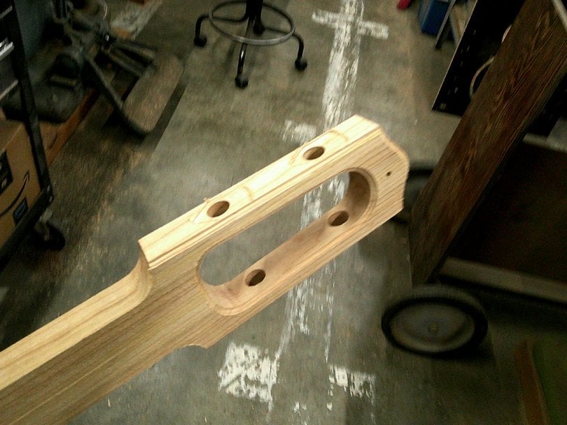
DSCF0916.JPG


...And on the back side. It adds some elegance to an otherwise simple form headstock.
 
Continuing on with the problem solving on the Pulga necks:

Adding some beautification to the headstocks:

View attachment 7508319

I'm putting an emblem on to the top of the headstock. The emblem itself is going to be cast from transparent red epoxy, and look like a faceted ruby. I need to rout a little recess for the emblem to be set into. I made up a quick fixture and routed the recesses in the three prototype necks.....

View attachment 7508320

They came out okay, but.....The shape and position wasn't quite right. So, I filled the recesses in the necks with epoxy, and started over.....

View attachment 7508321

So, I went ahead and built up the next fixture, which will do the beading cuts around the edges of the headstock. On this routing template, the headstock perimeter and inside shape are copied from the main routing template. This will guide the beading bit.

View attachment 7508323

Then I made up a good aluminum Master for the shape of the emblem inlay, and accurately located it on the back side of the template....

View attachment 7508322

And used the pin router to copy the recess onto the working side of the routing template.......

View attachment 7508324

There's the finished routing template for doing the two headstock operations: the emblem recess, and the beading.

View attachment 7508325

And there's its own dedicated fixture. Same design as the previous fixtures; a long MDF board with the MDF sliding strip.

View attachment 7508326

Both size necks fit on this fixture. Just two handle positions, because I'm only working the headstock area.

View attachment 7508327

Routing the inlay recess, using a 3/16" bit and 3/16" pin.

View attachment 7508328

Cutting the beading using a Freud 1/16" Beading Bit. I've removed the bearing, because the bit is now guided by the pin on the template underneath.

After cutting the beading on the top, I flip the neck over in the fixture and do the same cut on the back side of the headstock...

View attachment 7508369

Here's what the beading looks like, on the front side......

View attachment 7508370

...And on the back side. It adds some elegance to an otherwise simple form headstock.

Really digging the headstock detail ! Thanks for “taking us along” with the process, Bruce !
 
Hello everyone;

I've got a new R & D project going on here. I'm developing a new model of an Electric Upright Bass, from scratch, which I intend to build in production over the coming years. I'm doing this project working with a good friend of mine, Juan Perez, He came to me with the overall idea and design concept. I'm doing the R & D and engineering and tooling. The plan is that I'll be building these basses in batches and providing them to him in kit form. He'll be doing the finishing and assembly, and all of the marketing and sales and dealing with customers.

On here, I'm not going to talk too much about the design or features of the bass, or its value in the marketplace. That's another topic for another time and place. This thread is about the process of developing all the tooling, templates and fixtures for building the necks. I'm going to be building them almost completely with my Pin Routers, which you've probably seen in my thread about Pin Routers. And I plan to build them in batches of 5-10 at a time.

There is a process to developing a set of templates and fixtures, and that's what I'm showing here. And, by the way, this is all being done with no computers or CAD or CNC. Old School pencil layouts right on the MDF! I'm hoping that this will be useful to some of you in your projects.

We're developing two versions of this bass. The Pulga (Spanish for "Flea") is 35" scale, very portable. The Moscha ("Fly") is full size 41" scale. I'm doing the tooling for both of these necks at the same time. They have the same headstock, but different lengths and fingerboard dimensions.

Here are the basic templates:

View attachment 7501787

First, and most important, is the Master Drill Guide. It's a rectangular strip of MDF with four steel Drill Guide bushings pressed in. They are for a #30 size drill, which is a tiny bit over 1/8". I use 1/8" steel dowel pins to accurately locate everything during the whole production process. The Drill Guide is used to drill all the reference holes in all of the other templates and fixtures, and all the reference holes in every production neck. Everything fits together accurately, because they all come back to this one Drill Guide.

View attachment 7501788

At the headstock end of the Drill Guide, there's one bushing for the reference hole out on the tip of the headstock. The second bushing is for the pin to locate the outboard end of the fingerboard. These two holes are the same on both model necks.

View attachment 7501789

At the heel end of the Drill Guide, the two bushings are for the heel ends of the two different length necks. The same holes also locate the heel ends of the fingerboards.

View attachment 7501791

Next up is the Headstock Master Template. This is made from 1/2" Baltic Birch plywood. This is the sketchpad where I designed the headstock. I drew it out in pencil, full size, right on the plywood. Figured out the positions of the tuners, all the angles and contours. Then I went at it with Forstner bits, scroll saw, spindle sander and files. Took my time to get it perfect.

View attachment 7501790

Next up are the two main Routing Templates, one for each neck. They started out as straight strips of 3/4" MDF, and I did my initial pencil layouts of the whole neck on them. That's how I established the locations of the reference holes in the Drill Guide. In pencil. Then, after I made the Drill Guide, I used it to drill the actual reference holes in the Routing Templates.

That's the general theme here. I use these templates back and forth to make each other. To make sure that they all accurately line up with each other.

View attachment 7501792

The headstocks are the same on the two necks, so I used the Master Headstock Template in the pin router to make exact copies on the two Routing Templates. That's what pin routers are so good at. I'll show how I did that a little farther down.

And yes, that's a patch on the Pulga Routing Template. When trimming it up, I screwed up on the spindle sander and cut that blend radius too deep. So, I bandsawed that V-notch and glued in a scrap of MDF, then re-cut it. That's one reason that MDF is great for templates: It's easy to repair and modify.

View attachment 7501793

At the heel end of the Routing Templates are the slots for the Neck Bars. Same general idea as my legendary BruceBars, but going cross-wise. I cut the slots in my milling machine, while the templates were still rectangular strips.
It's great that you're sharing all this - thank you.
 
  • Like
Reactions: Bruce Johnson
Next up: Rough shaping the back of the neck.

I decided to do a rough shaping operation here in the process, using the pin router, before the fingerboard is glued on. I'll use a large 3/4" radius router bit to round off the main length of the neck. It'll take off most of the wood, and get it pretty close to the final shape.

After the fingerboard is on, I'll still have to do some blending and shaping around the transitions at both ends. For the first batch or two, I'll do that by hand with files. I'll be making up a special holding fixture to go in my Neck Horse, which you've probably seen before.

If you've been following my Pin Routers thread, I've been slowly working on a new special pin router which is made for fully shaping the backs of necks. It's an ongoing project, which I hope to get finished this summer. When it's operational, I'll be tooling it up to do the final shaping of the Pulga and Moscha necks. But I'll probably still do this rough shaping operation.

Also, the final shape of these necks is still an unknown. I personally don't have much experience playing electric uprights or acoustic uprights. I've taken a good guess at what it should be, in thickness and shape. When Juan gets the two prototypes in his hands, we'll adjust it and refine it. I'm deliberately leaving these two prototypes on the heavy/thick side, so I have room to carve and reshape them.

DSCF0912.JPG


To do the rough shaping operation, I'm going to use the two main routing fixtures that I've already built. On the underside of the fixture, I swap on a different template. The templates attach to the fixture by plugging onto the two dowel pins and putting in two screws. The new template is simple: the straight sides of the neck are copied from the main routing template, and then there are radiused stops at both ends. The template rides on the pin to guide the path of the radius router bit.

DSCF0913.JPG


On the top side of the fixture, the neck mounts face-down on the two dowel pins, and is held down by clamping blocks at both ends. I want some taper in the thickness of the neck, so I place this 1/8" masonite shim under the headstock. Later, If I decide I want more or less taper, I can change the thickness of that shim. 1/8" is a good guess starting point.

DSCF0914.JPG


The walnut Pulga prototype, clamped down and ready for the test cuts.....

DSCF0917.JPG


Making the cuts in the MGPR. Notice that I've removed the bottom bearing from the radius router bit. It's guided completely by the pin and the template.

DSCF0918.JPG


This is how the rough cut comes out. It leaves a shallow spine down the middle of the neck, and partial shapes at the transitions at both ends. These will be rounded off and blended in the final shaping.

DSCF0924.JPG


The walnut neck looked good, except for one problem: The stops at the heel end were too far back, so the final blending was going to get back into the neck pocket of the body. The stops need to be moved forward 1/2". That's why you do test cuts on prototypes.

So, I need to fix that now. More template repair. I fitted and glued blocks of MDF on both templates......

DSCF0925.JPG


Then measured and reshaped the stops.....As I said before, repairing and modifying MDF routing templates is easy.

DSCF0928.JPG


Doing the operation, with the corrected template, on the cherry Moscha neck. Standard procedure in the MGPR. Using the three handles to slide the fixture sideways. Down and back, 5 passes of 1/16" depth on each side of the neck. It took maybe 5 minutes. Even with the big dust collector running, the radius bit throws a lot of chips outside of the hood.

DSCF0926.JPG


It seems to all be good on both of the cherry prototype necks.

DSCF0927.JPG


This operation is in the books...

Next up are the neck bars and the fingerboards.
 
Last edited:
The next operation to be figured out is: Trimming the fingerboard blanks to size.

DSCF0929.JPG


Earlier in this thread, I showed how I made the two Fingerboard Templates. They are cut to the final plan size of the fingerboards, and have drill guide bushings, so I can also use them to accurately locate the dowel pin holes.

First, I use them as tracer templates. I've set them on the cherry board, figuring out how to position them on the board to get the best grain pattern look. And avoid cracks...I hold them down by hand and draw around them with a pencil.

DSCF0930.JPG


And bandsaw the blanks out, a little outside the pencil lines......

DSCF0931.JPG


Drilling the dowel pin holes: I set up the drill press with an 1/8" bit, depth stop set to drill halfway deep into the fingerboard blank. I hold the template on the blank, making sure that I'm drilling into the designated underside of it, and drill the hole down through the drill bushing......

DSCF0932.JPG


Then I plug in one of my handy L-pins, locking the template to the blank.

These L-pins are made from a short length of 1/8" piano wire, bent into an L-shape. Grind the lower tip into a slight taper, and wrap some black tape around the handle end. A very handy tool for temporarily pinning things together.

DSCF0933.JPG


With the pin locking the template in place, I drill the hole at the other end. Now the holes accurately match up with the holes in the neck.

DSCF0816.JPG


I forgot to take pictures, but I used this fixture, made previously, to trim the sides of all three fingerboard blanks. First on one side, then flipped over to the other side.

It worked fairly well, but I had a little trouble getting the depth set accurately. Some wiggling and lifting of the fixture on the table. When I get into production, I may abandon this fixture, and switch over to routing the sides and ends of the fingerboards in flat plan form, rather than up on edge. But these three fingerboards are okay for these prototype necks.
 
Last edited:
Putting in the Neck Bars, and gluing on the fingerboards:

DSCF0934.JPG


I've already routed the slots in the necks for the Neck Bars. But I need to drill the clearance holes for the bolts down through the bottom of the neck heel. This calls for a quick Special Tool! I quickly made up this Transfer Punch Guide from a scrap of aluminum bar stock......

DSCF0935.JPG


It plugs into the routed slot in the neck. I ground the ends to be a fairly snug fit. Three #30 holes.

DSCF0936.JPG


I plug my handy 1/8" transfer punch into the holes and give it a few light hammer taps.....

DSCF0937.JPG


Then drill the holes with a 5/16" Brad Point bit.

If you are wondering, the third center hole under the back bar is for a micro-tilt style adjusting screw, which comes up from the body and contacts against the underside of the bar.

DSCF0938.JPG


And here's three sets of the brass neck bars. You've seen how I make them before, over in the Metalworking thread.

DSCF0939.JPG


The bars are fitted in, with 10-32 cap screws filling the threads. Two short 1/8" plastic dowel pins. West Systems 105/206, dabbed on both surfaces, Clamped up face down on the Neck Beams.

DSCF0943.JPG


And there's the three prototype necks, with their fingerboard blanks glued on. Seeing the epoxy runoff on the sides of the fingerboards made me realize that it was pointless to rout the edges of the fingerboard before the glue-up. I really should be gluing them while oversized, and then routing the edges to make them clean and straight. This is what R & D is all about: Figuring out the best sequence to minimize the steps and labor in production.

DSCF0940.JPG


Getting ready for the last major step in building these necks: Cutting the 3 1/2" radius fingerboard surface. Over in my Pin Routers thread, you've seen me develop out this fixture for radiusing fingerboards in my MGPR pin router. It works very well. But now I have to adapt it to hold the Pulga and Moscha necks. The shorter Pulga neck isn't much of a problem.....

DSCF0941.JPG


But the longer 41" scale Moscha neck won't fit! It's too long......

DSCF0942.JPG


So, I've got to figure out how to lengthen the carriage of the fixture to handle it....

That's tonight's work assignment......
 
Modifying the Fingerboard Radiusing Fixture to fit the Pulga and Moscha necks:

DSCF0947.JPG


I made up a new cradle for the fixture from a 4" wide strip of Baltic Birch plywood. It's long enough to handle either neck. I mounted the two 3 1/2" radius MDF end blocks to it, after measuring and adjusting their height. These fingerboards have a lot of vertical taper, 5/16" lower at the nut. I trimmed down the headstock end block to build that in to the fixture.

The necks mount to the cradle on two dowel pins, plus two 10-32 screws at the heel, up into the rear neck bar, plus a maple clamp block on the headstock. Here's the Pulga neck mounted.

DSCF0948.JPG


And here's the Moscha neck.

DSCF0950.JPG


On the fixture, I raised up the heel end radius block, with a rectangle of 3/4" MDF under it.......

DSCF0949.JPG


And did something similar at the headstock end, but making the spacer block offset, to gain the additional length....

DSCF0951.JPG


Check fitting the new carriage in the fixture. I had to do some extra trimming at the headstock end to get enough clearance as the carriage tilts to either side.

DSCF0952.JPG


Checking it out with the big Moscha neck mounted.....

DSCF0953.JPG


Checking the full tilt one way.......

DSCF0954.JPG


And the other way......All looks good, it tilts far enough to complete the radius.

DSCF0955.JPG


Then I made up this maple extension to the lever beam, to fit up the aluminum link at the headstock end. This extension is easily removable to convert the fixture back for my regular Scroll Bass necks.

That's about it for the mods. A few more little details and I'll be ready to radius the fingerboards.
 
Testing the Fingerboard Radiusing Fixture! This is where it gets exciting! If you are excited by Pin Routers and complicated fixture building....

DSCF0956.JPG


A few more adjustments and details. I trimmed down the height of the cradle end block to raise up the heel of the neck slightly. This puts the uncut surface of the fingerboard about 0.040" above the height of the radiused end block. The end block is 3 1/2" radius, and is even with final cut of the surface.

DSCF0957.JPG


I added index marks and an aluminum pointer, so I can keep track of the cradle rotation angle.

DSCF0958.JPG


Setting it up in the MGPR: A short 1/2" router bit, table lowered, the T-bearing pin........

DSCF0959.JPG


Checking and setting the final cut height at the heel end. I zero the depth gauge and raise the spindle up 1/4".......

DSCF0960.JPG


Router-cutting the radiused surface on cherry Moscha neck. The cherry is easy and enjoyable to rout; no lugging or burning. I did the routing in 3 depths of cut passes, leaving it 0.030" high. Then stop and check the dimensions....

DSCF0961.JPG


It went smoothly, no real problems. There's more detailed coverage of how this fixture works over in the Pin Routers thread. If you are interested....

DSCF0962.JPG


Checking it out, I'm realizing that the fingerboard is still too thick at the nut end. I need to take it down an 1/8" or more. Now is the time to make the adjustment in the fixture itself, by trimming down the end block some more. This is the R & D of tooling up to build a bass neck. Test cuts, measurements, corrections to fixtures. Developing the design of the instrument as I go.

DSCF0963.JPG


Everything else looks good, the fingerboard just needs some more vertical taper.

DSCF0964.JPG


The heel end looks good. It's still 0.030" high.
 
Finishing up with the fingerboard radiusing operation:

DSCF0965.JPG


One more mod to the fixture, for ease of operation: I moved the angle-adjusting lever and link down closer to the heel end. It had been in the middle of the length of the fixture. To change to the next angle position, at the end of each pass, I had to let go of the handles and take two steps around the end to reach the lever. A waste of time and energy! Now I can change the angle with my right hand, standing at the back end of the fixture.

DSCF0966.JPG


I recut the surface of the long Moscha neck, with the increased vertical taper. That brought the thickness at the nut end down to where I wanted it.

DSCF0967.JPG


The settings for the Moscha neck are dialed in and complete.

DSCF0968.JPG


Then I went through the same operation on the two Pulga necks, using the same final depth setting and cut sequence....

DSCF0970.JPG


And here's the three necks, all radiused. After checking all the dimensions, I'm going to take one more pass on the two Pulga necks, with a shim under the headstock to add a bit more taper; reducing the thickness at the nut end by another 0.060". I may as well make the thickness the same on the Pulga and Moscha necks, so they can use the same nut.

DSCF0971.JPG


The heel ends look good; equal thickness and even side-to-side.

DSCF0969.JPG


Here's the final configuration of the Fingerboard Radiusing Fixture, as set up for doing these necks. Now it will go back on the shelf, until I need it next time. I have a special big shelf reserved for it.

There's a fair investment of time in building a complex fixture like this. But it's worth it. It pays off in labor savings in 2-3 necks. And I expect to be using this fixture to cut fingerboards for all of my basses for many years.

These necks are almost done! Only a few operations left, which don't require much tooling.
 
Speaking from a perspective of absolute lack of knowledge, I’m curious about how you are dealing with relief. Will you have a truss rod (will the neck flex at all?), or will you be building in some scoop? I have a Stagg EUB, it has a truss rod that seems to have absolutely no effect whatsoever, and the scoop needs some attention as while much of the neck is fine, the E is choking on some notes, particularly at Bb. Fortunately I was given the name of a good bass luthier locally, who has done work for Tony Levin, so I don’t have to figure out how to ship it anywhere (the neck is not removable, it’s part of the body).
 
  • Like
Reactions: HofnerVox
Speaking from a perspective of absolute lack of knowledge, I’m curious about how you are dealing with relief. Will you have a truss rod (will the neck flex at all?), or will you be building in some scoop? I have a Stagg EUB, it has a truss rod that seems to have absolutely no effect whatsoever, and the scoop needs some attention as while much of the neck is fine, the E is choking on some notes, particularly at Bb. Fortunately I was given the name of a good bass luthier locally, who has done work for Tony Levin, so I don’t have to figure out how to ship it anywhere (the neck is not removable, it’s part of the body).

That's a very good question, Bob. These necks have no truss rods. They are thick necks and fingerboards, and you may have noticed that they don't have long overhanging ends of the fingerboards, like Baby Basses and many other EUB's. The purpose of the truss rod in a Baby Bass neck is to adjust the overhanging end, if it moves up or down. I deliberately designed these necks with very long heels that fully support the fingerboard out to the end. These necks should be very solid and stable against short term and long term movement.

As far as pre-cutting some relief into the first few positions of the fingerboards, I'm starting out not cutting any into these necks. They are flat, cylindrical 3 1/2" radius. I'm not sure the customers actually want it. We'll find out during testing. And I can add it later if needed.
 
Continuing on with this project, I spent a few weeks figuring out the body for the Pulga, and making up all the pin routing fixtures for it. I did all the design work on the bench, with pencil and ruler measurements right on the boards. This is a very minimalist body, and the biggest issue was squeezing everything into the smallest size.

DSCF0992.JPG


I decided to make the body from three horizontal boards, with most of the routing done before gluing them together. I made the prototype from walnut, to go with that walnut neck that I built. The three walnut boards are from leftovers that I had lying around, and don't really match each other. But that's okay, I'm going to be keeping this 1st prototype for myself, as a test bed and occasional player.

The production bodies will be made from cherry, same as the necks.

DSCF0990.JPG


Here's what the body looks like, the three boards pinned together for a check fit.

DSCF0989.JPG


As with the neck, the boards are all aligned by two dowel pins, plugged into 1/8" reference holes, which are used to lock the board blanks into the routing fixtures.

DSCF0991.JPG


I put the control cavity into the side of the body, routing it halfway into the underside of the mid-board, and half into the top of the bottom board. An aluminum plate will screw down over it, holding the pots and the output jack.

I won't go over the whole process of making the tooling, but it's the same general method that I used on the neck. A Master drill fixture to accurately locate the important holes. Routing templates made from MDF, attached to the underside of routing fixtures made from plywood. The body boards pin down to the top of the fixtures, and I use the two rubber handles to maneuver them around in the MGPR Pin Router.

DSCF0972.JPG


Here's the Master Drill Guide; MDF with steel drill guide bushings pressed in. This locates the all-important Reference Holes, and the pilot holes for the neck bolts.

DSCF0974.JPG


Making up the routing template for cutting the neck pocket in the top board. It's a strip of MDF.

DSCF0973.JPG


I screwed two strips and two blocks to the bottom side, then flipped it over and put it in the pin router to cut the pocket in the template.

DSCF0975.JPG


And here's the fixture in the MGPR. The routing template is pinned to the underside of the plywood. On the top, I mounted an MDF board which is tilted up to the angle that the neck pocket needs to be. The walnut top board is pinned down, ready to rout!

DSCF0976.JPG


And there's the finished neck pocket. Maybe 3 minutes of routing time.
 
Last edited:
More of the fixtures for routing the Pulga's body:

I made up 5 routing fixtures for the body, all in the same general form. A strip of plywood, 10" wide x 36" long. The 3/4" MDF routing template attaches to the bottom side with two pins and two screws. It can easily be removed to be touched or modified. Or swapped to do a different operation.

Also on the bottom side is a strip of 3/4" plywood, which acts as a slide rail. It keeps the fixture flat on the pin router's table, so it can't rock or tip. Under the strip are two T-nuts that the rubber handles screw into on the top.

DSCF0978.JPG


This fixture cuts several of the internal pockets for the clamp bars and the control cavities.

DSCF0979.JPG


Here it is in operation in the MGPR, routing the slots for the clamp bars in the top surface of the mid-board.

DSCF0977.JPG


Routing the control cavity in the underside of the mid-board. The two Reference Holes in the boards are on the centerline, and are drilled all the way through. So, the boards can be flipped over in the fixture to make cuts on the top or bottom side. This is all part of the Engineering; working out the best sequence of operations with the least number of fixtures and templates.

DSCF0981.JPG


This fixture routs the perimeter of all three body boards.

DSCF0982.JPG


Here it is in operation, trimming the perimeter of the top board. I then use the same fixture to do the beading around the top edge, using a small beading bit.

DSCF0983.JPG


Cutting the trough in the bottom side of the bottom board, with a 3/4" cove bit. This trough is for the sliding tube peg, which clamps on the back side of the body.

DSCF0984.JPG


The underside of the fixture for routing the peg trough; a straight slot made with two strips of plywood, spaced for the 3/8" pin to slide through.

DSCF0985.JPG


Routing the pockets for the peg clamp bars, after routing the trough.
 
And here's the body after epoxying the three parts together:

DSCF0995.JPG


As I saw with the neck, there was more epoxy squeezeout than I anticipated. The body isn't ruined, but it's extra labor cleaning up all those surfaces and holes.

DSCF0996.JPG


I clamped it up with the top side up, so the epoxy didn't mess up the top surface or the beading......

DSCF0997.JPG


But it oozed into the peg trough and the holes on the bottom. It can all be fixed, but I don't want to be doing this on every production instrument.

So, I'm going to go back and rearrange the process. I'll rout the internal pockets on the middle board, and then epoxy the boards together. And then rout all the external stuff, like the perimeter, the neck pocket, the beading, and the peg trough. It'll require a few changes to the fixtures, to hold the full-thickness body during the routing.

That's what this R & D phase is all about. Figuring out the best most efficient process. It's worth the time investment to make these changes now.

This walnut body will have a few scars and patches, but it will be fine for the prototype.
 
More engineering and tooling for the same project:

I decided to mount the pickup coils for the Pulga hidden inside a wood block. Obviously, a good job for the Pin Router!

DSCF0006.JPG


A special routing fixture, with an MDF routing template mounted on the bottom.....

DSCF0005.JPG


And the walnut blank fits on top, on two steel 1/8" dowel pins.......Two of the rubber handles screw down to T-nuts in the corners.

DSCF0007.JPG


In use in the MGPR.........1/4" bit, 1/4" pin. Gentle passes, 1/16" deep, because it's a deep cut with thin walls.....

DSCF0008.JPG


And there's the prototype part, routed......

DSCF0009.JPG


Trimmed out, screw holes drilled, check fitting with the two coils......

DSCF0011.JPG


Lining the inside with copper shielding tape.......

DSCF0015.JPG


Assembled in a vise with an aluminum plate on the side face, and poured full of clear epoxy.....

DSCF0016.JPG


Cured and cleaned up......

DSCF0019.JPG


This is the prototype to go on the walnut Pulga, so I made the block from walnut. The production ones will be made from cherry. Also, I'll probably use black-pigmented epoxy on the production ones. But the clear epoxy look cool on this one.

DSCF0018.JPG


And here's what it looks like from the outside.......just a simple smooth, rounded block of wood.
 
Is the cover held on the routing jig just with the pins or do you double stick tape it or anything?

Just the pins. They are 1/8" steel dowel pins 1 1/4" long, sticking up 1/2" above the fixture surface. I drilled the holes in the walnut block to #30 and pushed it down on the pins by hand. That seems to be enough friction to hold it in place during the routing. I was watching it as I was routing to see if it would lift up.

If I have a problem in production, I can always add two bolts and clamp blocks to hold it down by the outer ends of the block.
 
  • Like
Reactions: Matt Liebenau
Meanwhile, back on the necks:

Here's another very important fixture that needed to be made up:

DSCF0020.JPG


Most of you have seen my Neck Horse on other threads around here. It's a big contraption that clamps to the front of my woodworking bench, and holds a neck in a solid position for shaping and sanding. For the Pulga project, I needed to make up a custom holding fixture, which clamps into the Neck Horse. It's built up from scraps of MDF and plywood. The spine down the center is only 1 1/2" wide.

Here's the walnut prototype neck, clamped face down, ready for the finish shaping of the back.

DSCF0022.JPG


This fixture gives full access for filing and shaping the back.

By swapping around some parts on the fixture, I can also mount the neck face up, for sanding and finishing the fingerboard surface.
 
Last edited:

Latest posts