I'll finish geting my observations of the circuit written up in the next few days, but for me, an input impedance switch to go from the designated 220K to a higher input Z makes sense. The 220K value for when the wonderful voicing Charlie has designed is used, the 1 meg, or so, for when one is just enhancing the existing passive bass sound. Input Z would be an additional switch for me, because I find the in/out of circuit switch very useful for evaluating what I've dialed up.

Enjoy the benefits of a premium membership!
Upgrade Account
-
TalkBass has been independent since 1998. Add your voice.
Create a free account to reply to discussions, view embedded media, and browse with fewer display ads.
Join free Log in
Want zero display ads or expanded classifieds tools? Compare plans.
You are using an out of date browser. It may not display this or other websites correctly.
You should upgrade or use an alternative browser.
You should upgrade or use an alternative browser.
The Passinwind Open Source Preamp
- Thread starter Passinwind
- Start date
More options
Who Replied?

- Dec 3, 2003
- 23,044
- 45,901
- Disclosures
- Designer/Toaster Tech @ Passinwind Electronics
I'll finish geting my observations of the circuit written up in the next few days, but for me, an input impedance switch to go from the designated 220K to a higher input Z makes sense. The 220K value for when the wonderful voicing Charlie has designed is used, the 1 meg, or so, for when one is just enhancing the existing passive bass sound. Input Z would be an additional switch for me, because I find the in/out of circuit switch very useful for evaluating what I've dialed up.
An input Z switch right at the input jack would be especially easy to implement. A considerably lower value than 200k often works well if there's already another preamp in front of the box too, I use 20k-ish in some of my amps and rack preamps.
This image from Helmuth Lemme shows the effect of various input impedances and a passive PU.
Not sure of protocol here at Talkbass, here is a gif and a link, I hope.
http://www.buildyourguitar.com/resources/lemme/secrets14.gif
So in the "enhance existing sound mode" having a high Z input is useful for keeping the sound of the first stage of a passive PU. When using the resonance capability of the circuit more fully, the low Z scrubs of the native resonance of the PU to allow the circuit resonance to function cleanly.
Not sure of protocol here at Talkbass, here is a gif and a link, I hope.
http://www.buildyourguitar.com/resources/lemme/secrets14.gif
So in the "enhance existing sound mode" having a high Z input is useful for keeping the sound of the first stage of a passive PU. When using the resonance capability of the circuit more fully, the low Z scrubs of the native resonance of the PU to allow the circuit resonance to function cleanly.
Attachments


Passin Wind tone box? Yep, I tried a few!
Sound nothing like any EQ you've used before with the exception of Pultec.
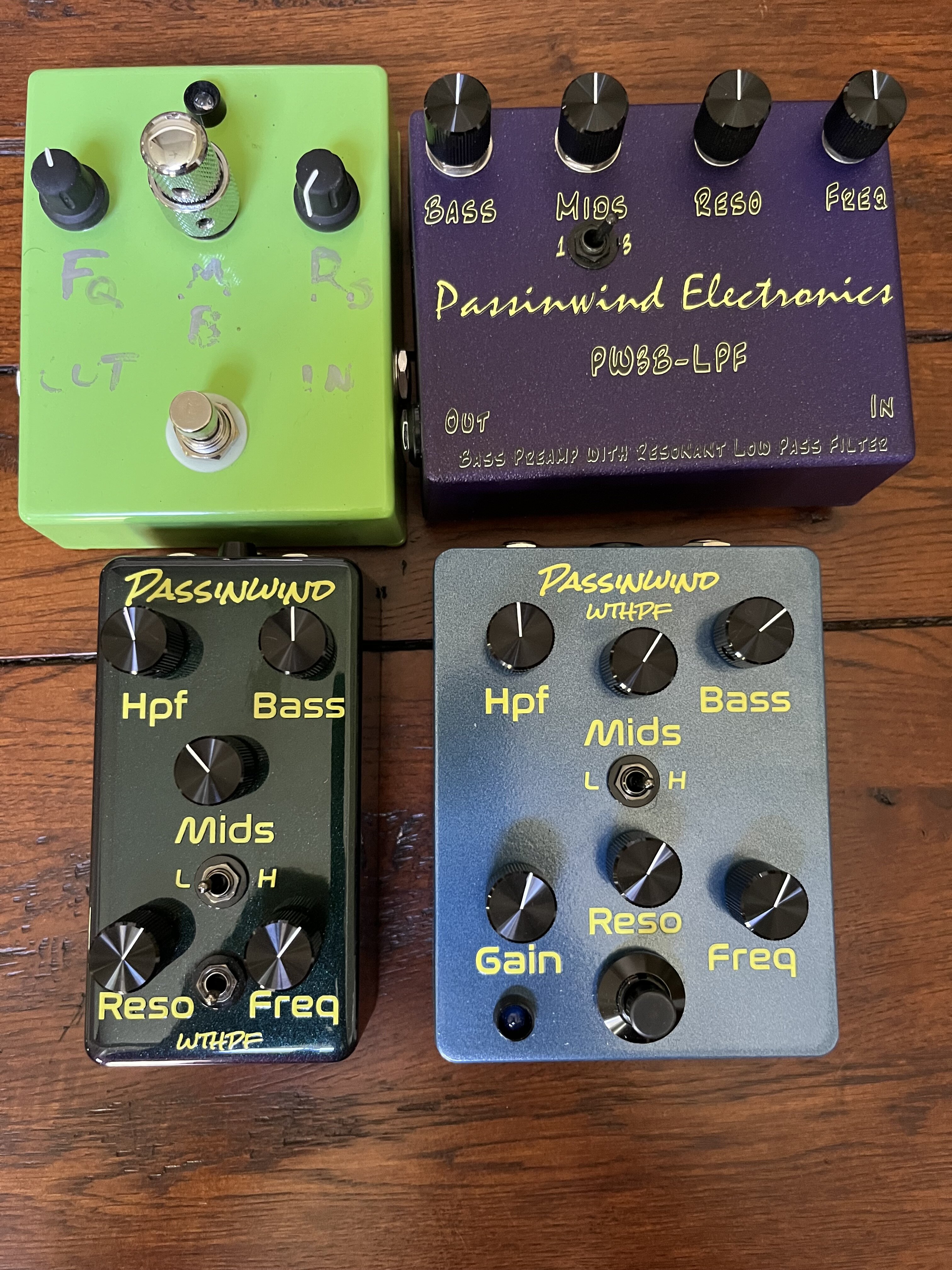
Sound nothing like any EQ you've used before with the exception of Pultec.
Lemme's website is pretty useful describing the effects of the first stage that a passive PU sees. The sister file to the image above is why wiring the opamp after the passive tone cap sounds different than opamp after the PU feeding a passive network, ala Pultec. One can adjust the frequency of passive resonance by switching in different value caps and the amount of boost at resonance with a shunting resistor. The PW3B is a much more flexible way to do that.
In my limited experience, both the PW3B and the Pultec share being able to do significant manipulations without losing the character of the sound.
In my limited experience, both the PW3B and the Pultec share being able to do significant manipulations without losing the character of the sound.
Attachments

Well that's a pretty interesting collection, JimC. 
Shows me how important graphics are.
Are the top two v1 circuit? Do you have any characterization of v1 compared to v 2?
Shows me how important graphics are.
Are the top two v1 circuit? Do you have any characterization of v1 compared to v 2?
I'll go first.
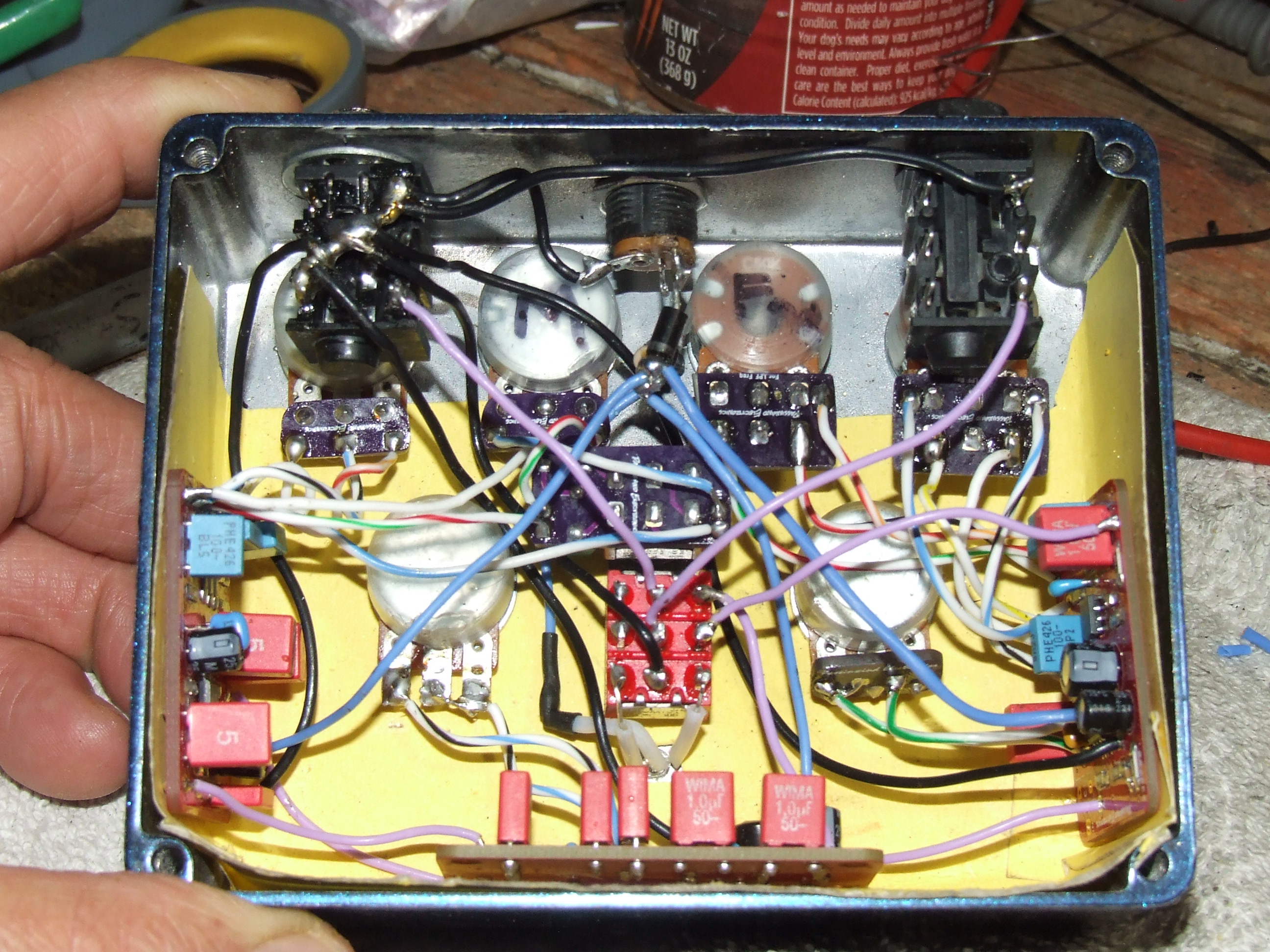 Point to point. File folder cardboard to insulate the surfaces.
- Dec 3, 2003
- 23,044
- 45,901
- Disclosures
- Designer/Toaster Tech @ Passinwind Electronics
Well that's a pretty interesting collection, JimC.
Shows me how important graphics are.
Are the top two v1 circuit? Do you have any characterization of v1 compared to v 2?
Top left is stock v1, built by another TB'er, top right is a one-off battery powered v1.8 that Jim finds too dark, bottom left is a v3, bottom right a v4 similar to yours. V2 is the single board 125B format one, which only @Tassieviking and I have any direct experience with so far. I should probably send a v2 one to Jim C once we finalize the initial default spec, his feedback is always useful.
I’d be interested in buying a box that had a mute switch with absolutely no pop when switching instruments and an XLR DI output to the mixer (with ground lift switch). Maybe it’s time for a survey thread
 for those who will build versions for general users.
- Dec 3, 2003
- 23,044
- 45,901
- Disclosures
- Designer/Toaster Tech @ Passinwind Electronics
I’d be interested in buying a box that had a mute switch with absolutely no pop when switching instruments and an XLR DI output to the mixer (with ground lift switch). Maybe it’s time for a survey thread
You're definitely not the first person to ask for those two things. If I did them to my usual standards (i.e. a Jensen DI transformer and a relay switcher board) it'd add at least $100 in parts cost, FWIW. Should fit in a 1590BBS case, but probably nothing smaller if using the current gen 3/4 boards. But anyone who might want to build and sell these things can of course design and add any circuity and features they care to, it's all open source.
A DI was never mandatory for me as I have both passive and active boxes and like the sonic qualities of both for different reasons. I could see how others might want a one box does all.I’d be interested in buying a box that had a mute switch with absolutely no pop when switching instruments and an XLR DI output to the mixer (with ground lift switch). Maybe it’s time for a survey thread
Wouldn't it take more than a standard switch for a 100% guaranteed noiseless switching?

I think that's what PW stated with the "relay switcher board" in the above comment.A DI was never mandatory for me as I have both passive and active boxes and like the sonic qualities of both for different reasons. I could see how others might want a one box does all.
Wouldn't it take more than a standard switch for a 100% guaranteed noiseless switching?
Dadum said:
"I’d be interested in buying a box that had a mute switch with absolutely no pop when switching instruments and an XLR DI output to the mixer (with ground lift switch)."
A balanced out is nice for a DI to feed the house, and also to feed a power amp, directly. Makes for a very portable rig.
Charlie said:
"If I did them to my usual standards (i.e. a Jensen DI transformer... "
Please, do you mean a passive setup with a JT DB E at the input or fed the output, or an active line out taping the signal after the first stage of the HPF, going to it's own driver and a 1:1 line out xfmr , or... ?
Are you going with a transformer for the galvanic isolation needed for ground lift, or because you've found that an op amp based transformer-less design is not as good, sonically?
If one wished to have balanced output from the PW3B, to feed only a power amp, not a second DI feed, does one need ground lift capability? If not, is there a public circuit, widely agreed to be transparent, in which one might use, say, an OPA 1642 for a quality transformer-less output ?
Thanks
"I’d be interested in buying a box that had a mute switch with absolutely no pop when switching instruments and an XLR DI output to the mixer (with ground lift switch)."
A balanced out is nice for a DI to feed the house, and also to feed a power amp, directly. Makes for a very portable rig.
Charlie said:
"If I did them to my usual standards (i.e. a Jensen DI transformer... "
Please, do you mean a passive setup with a JT DB E at the input or fed the output, or an active line out taping the signal after the first stage of the HPF, going to it's own driver and a 1:1 line out xfmr , or... ?
Are you going with a transformer for the galvanic isolation needed for ground lift, or because you've found that an op amp based transformer-less design is not as good, sonically?
If one wished to have balanced output from the PW3B, to feed only a power amp, not a second DI feed, does one need ground lift capability? If not, is there a public circuit, widely agreed to be transparent, in which one might use, say, an OPA 1642 for a quality transformer-less output ?
Thanks
- Dec 3, 2003
- 23,044
- 45,901
- Disclosures
- Designer/Toaster Tech @ Passinwind Electronics
Dadum said:
"I’d be interested in buying a box that had a mute switch with absolutely no pop when switching instruments and an XLR DI output to the mixer (with ground lift switch)."
A balanced out is nice for a DI to feed the house, and also to feed a power amp, directly. Makes for a very portable rig.
Charlie said:
"If I did them to my usual standards (i.e. a Jensen DI transformer... "
Please, do you mean a passive setup with a JT DB E at the input or fed the output, or an active line out taping the signal after the first stage of the HPF, going to it's own driver and a 1:1 line out xfmr , or... ?
Are you going with a transformer for the galvanic isolation needed for ground lift, or because you've found that an op amp based transformer-less design is not as good, sonically?
If one wished to have balanced output from the PW3B, to feed only a power amp, not a second DI feed, does one need ground lift capability? If not, is there a public circuit, widely agreed to be transparent, in which one might use, say, an OPA 1642 for a quality transformer-less output ?
Thanks
Any of those approaches can work well, a JTDBE at the input or a line level one somewhere later are just super easy to implement, “sexy”, and generally the most foolproof. I’ll investigate a few different DIY active DI boards, I know they’re out there.
What's the inside look like?
About like so for the moment:
- Dec 3, 2003
- 23,044
- 45,901
- Disclosures
- Designer/Toaster Tech @ Passinwind Electronics
Update:
This week I've been testing V2 boxes with TL072 opamps, which I think will become the default choice. Finished up a new build spec yesterday that correlates really well with the LTspice model, hopefully this will be "the one."
And then I did a bunch of work on a two V4 blend format for my dojo, and am ordering a new blender board for that project this morning. One of the guys at the weekly jam I play has both an acoustic guitar and a dobro with similar piezo/mag pickup formats, which should speed testing up quite a bit. This has also been a good excuse to get back to the little DSP boards that I've had waiting on a job for a few years now. The resonator pickup through chorus and delay is super fun and the whole mess sounds pretty great for being a first try.
Planning on (finally!) having the V4 documentation wrapped up in a few days, the same boards will work for V3 builds as well. The graphics and drill files from @dcoyle's build will be up on GitHub for those who want to use AmplifyFun, who I highly recommend.
This week I've been testing V2 boxes with TL072 opamps, which I think will become the default choice. Finished up a new build spec yesterday that correlates really well with the LTspice model, hopefully this will be "the one."
And then I did a bunch of work on a two V4 blend format for my dojo, and am ordering a new blender board for that project this morning. One of the guys at the weekly jam I play has both an acoustic guitar and a dobro with similar piezo/mag pickup formats, which should speed testing up quite a bit. This has also been a good excuse to get back to the little DSP boards that I've had waiting on a job for a few years now. The resonator pickup through chorus and delay is super fun and the whole mess sounds pretty great for being a first try.
Planning on (finally!) having the V4 documentation wrapped up in a few days, the same boards will work for V3 builds as well. The graphics and drill files from @dcoyle's build will be up on GitHub for those who want to use AmplifyFun, who I highly recommend.
- Dec 3, 2003
- 23,044
- 45,901
- Disclosures
- Designer/Toaster Tech @ Passinwind Electronics
This week's diversion: a breakout/blender box for my dobro/banjo hybrid. The blend board could be readily adapted to Ric-O-Sound applications and the like as well, or used onboard for summing two LPFs in per-pickup builds.
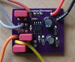
Mix/blend board, actual size just under 1 x 1.25 inches:
Quick and dirty test setup:
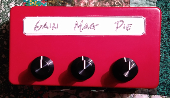
TRS input is on right, tip is magnetic pickup and ring is piezo on resonator. Mag input goes to unbuffered Mag send jack on front, then to WTHPF pedal, returning on Mag return jack and on to Mag level control. Piezo side goes to standalone HPF/buffer, which outputs directly to Pie level control. Blended output jack is TS and on the "top". So the bottom jacks can function as an EFX loop for the magnetic pickup, or as a send to a second amp. I have many many other configs in mind, this is just tailored for my Friday night jam scene where even two pedals feels a bit intrusive. It already works really well with my AudioKinesis 112 and DIY amp and preamp, I will work up a demo soon.
I am finishing up the v4 schematics right now, and tweaking the new board layouts, all of which I plan to have up on GitHub by week's end. I'll get back to v2 ASAP, it's still not quite a stable as it needs to be and probably needs to be de-tuned a little to get there for DIY builders. V4 has been rock solid and andy remaining tweaks are likely to be about enhancing control feel as much as possible, as different test versions have all brought different play feels. I think the version I helped @dcoyle with is going to be very close to the default spec, that was/is an especially good one.
Mix/blend board, actual size just under 1 x 1.25 inches:
Quick and dirty test setup:
TRS input is on right, tip is magnetic pickup and ring is piezo on resonator. Mag input goes to unbuffered Mag send jack on front, then to WTHPF pedal, returning on Mag return jack and on to Mag level control. Piezo side goes to standalone HPF/buffer, which outputs directly to Pie level control. Blended output jack is TS and on the "top". So the bottom jacks can function as an EFX loop for the magnetic pickup, or as a send to a second amp. I have many many other configs in mind, this is just tailored for my Friday night jam scene where even two pedals feels a bit intrusive. It already works really well with my AudioKinesis 112 and DIY amp and preamp, I will work up a demo soon.
I am finishing up the v4 schematics right now, and tweaking the new board layouts, all of which I plan to have up on GitHub by week's end. I'll get back to v2 ASAP, it's still not quite a stable as it needs to be and probably needs to be de-tuned a little to get there for DIY builders. V4 has been rock solid and andy remaining tweaks are likely to be about enhancing control feel as much as possible, as different test versions have all brought different play feels. I think the version I helped @dcoyle with is going to be very close to the default spec, that was/is an especially good one.
Last edited:
Hey, Charlie, glad your having fun.
I've been dinking around, trying to write something up about the 4.7 version, but only got as far as the HPF, shown below. My comments are intended as an intro to the box for someone like myself, a year ago, when I came across the thread and knew nothing about it and read through ~60 pages to figure it out. My comments are too long for anyone that knows what's going on, but I thought the thread had wound down.
Bottom line, in my very humble opinion, I wish the F3 of the HPF were a little lower.
The start of my rant :
I've had some time with a 4.7 version of Charlie Escher's PassinWind PW3B-LPF bass pre, pictured in posts 1272 and 1287. It includes three small circuit boards: a v1.8 variable frequency high pass filter (HPF); a v6.4 Baxandall with bass and mid boost/cut controls and a 3 position mid frequency switch; and a v5.5 variable frequency and variable resonance low pass filter (LPF), with variable makeup gain.
It runs on 9 volts and has room for a battery in a 1590BB2 enclosure, although I didn't try to build one in. I believe the v4.7 I'm using has been further revised, and the later version is what may be shared at Passinwind on github. I bought an enclosure and had it drop-shipped to AmplifyFun, where they drilled and painted graphics on it, per Passinwind's file. I believe this file will also be available at github. AmplifyFun were good, quick and cheap. Thanks.
This is a very flexible, very musical, very quiet bass pre. It is well worth the effort to build. Others can tell you how close it can get to a particular sound, Alembic, Ampeg, etc. What I can report is that I always find an enhancement in there to make me happy with my sound.
I am very grateful to Charlie for sharing this design and for much help on my box.
I am also respectful of his circuit. These are not cookbook filters, but a result of many hours of modeling and musical judgment on Passinwind's part.
For someone thinking about building this bass pre I'll try to describe a bit of what it does, from my point of view. Charlie, please correct me where I'm off.
First is a high pass filter, which is useful to protect speakers from low frequency energy, or restrict bandwidth to not go muddy, or to leave a space for a kick drum, or... Because of the way the HPF is implemented on the PW3B, there is also the ability to control bass resonance near the cutoff frequency.
The usual LPF uses a classic filter alignment like a B3 or a 4th order L-R, allowing you to shift the high pass frequency while keeping the slope the same. In the PW HPF, "Freq" shifts the -3dB point of the four stage high pass filter, but does so by changing the Q, (the amount of damping or resonance at the lower end), around a more or less fixed frequency. When the control is CW the resonance is very damped, the slope is shallower and it's -3dB is at a higher frequency. Full CCW and there is a smooth boost in the lows before dropping steeply for a -3dB in the lower bass. It can help an over damped (low Qt, like <.3) MI bass speaker, without adding too-deep frequencies, as a plateauing Bax bass boost does.
It's great to be able to make the bass sound fat or lean, as wanted.
The in/out-of-circuit bypass switch helped me notice that the lower frequencies of the E string were lessened by the HPF, although, because of the boost just above the rolloff, it didn't sound bass shy. Just the thing for playing loudish.
Over time I came to wish there were an option to set the HPF to a lower frequency, so I could twiddle the fat/lean thing without losing the deeper extension of having no HPF in circuit. Because this is a such a refined circuit I'm reluctant to try to mod it myself for a lower high pass point. Charlie has mentioned considering using a switch to shift frequency on his own box. If that were lower, and it becomes available, I would gladly adopt it.
Simply bypassing the LPF and feeding the input to the next stage, the Bax, won't work for me because the Bax input impedance is only 36K, or so, which is too low for a passive pickup input, IMO.
I built a buffer to be able to bypass the HPF rather than mod it, and to give a higher input impedance for passive pickups.
(as far as I got.... )
Dan
I've been dinking around, trying to write something up about the 4.7 version, but only got as far as the HPF, shown below. My comments are intended as an intro to the box for someone like myself, a year ago, when I came across the thread and knew nothing about it and read through ~60 pages to figure it out. My comments are too long for anyone that knows what's going on, but I thought the thread had wound down.
Bottom line, in my very humble opinion, I wish the F3 of the HPF were a little lower.
The start of my rant :
I've had some time with a 4.7 version of Charlie Escher's PassinWind PW3B-LPF bass pre, pictured in posts 1272 and 1287. It includes three small circuit boards: a v1.8 variable frequency high pass filter (HPF); a v6.4 Baxandall with bass and mid boost/cut controls and a 3 position mid frequency switch; and a v5.5 variable frequency and variable resonance low pass filter (LPF), with variable makeup gain.
It runs on 9 volts and has room for a battery in a 1590BB2 enclosure, although I didn't try to build one in. I believe the v4.7 I'm using has been further revised, and the later version is what may be shared at Passinwind on github. I bought an enclosure and had it drop-shipped to AmplifyFun, where they drilled and painted graphics on it, per Passinwind's file. I believe this file will also be available at github. AmplifyFun were good, quick and cheap. Thanks.
This is a very flexible, very musical, very quiet bass pre. It is well worth the effort to build. Others can tell you how close it can get to a particular sound, Alembic, Ampeg, etc. What I can report is that I always find an enhancement in there to make me happy with my sound.
I am very grateful to Charlie for sharing this design and for much help on my box.
I am also respectful of his circuit. These are not cookbook filters, but a result of many hours of modeling and musical judgment on Passinwind's part.
For someone thinking about building this bass pre I'll try to describe a bit of what it does, from my point of view. Charlie, please correct me where I'm off.
First is a high pass filter, which is useful to protect speakers from low frequency energy, or restrict bandwidth to not go muddy, or to leave a space for a kick drum, or... Because of the way the HPF is implemented on the PW3B, there is also the ability to control bass resonance near the cutoff frequency.
The usual LPF uses a classic filter alignment like a B3 or a 4th order L-R, allowing you to shift the high pass frequency while keeping the slope the same. In the PW HPF, "Freq" shifts the -3dB point of the four stage high pass filter, but does so by changing the Q, (the amount of damping or resonance at the lower end), around a more or less fixed frequency. When the control is CW the resonance is very damped, the slope is shallower and it's -3dB is at a higher frequency. Full CCW and there is a smooth boost in the lows before dropping steeply for a -3dB in the lower bass. It can help an over damped (low Qt, like <.3) MI bass speaker, without adding too-deep frequencies, as a plateauing Bax bass boost does.
It's great to be able to make the bass sound fat or lean, as wanted.
The in/out-of-circuit bypass switch helped me notice that the lower frequencies of the E string were lessened by the HPF, although, because of the boost just above the rolloff, it didn't sound bass shy. Just the thing for playing loudish.
Over time I came to wish there were an option to set the HPF to a lower frequency, so I could twiddle the fat/lean thing without losing the deeper extension of having no HPF in circuit. Because this is a such a refined circuit I'm reluctant to try to mod it myself for a lower high pass point. Charlie has mentioned considering using a switch to shift frequency on his own box. If that were lower, and it becomes available, I would gladly adopt it.
Simply bypassing the LPF and feeding the input to the next stage, the Bax, won't work for me because the Bax input impedance is only 36K, or so, which is too low for a passive pickup input, IMO.
I built a buffer to be able to bypass the HPF rather than mod it, and to give a higher input impedance for passive pickups.
(as far as I got.... )
Dan
- Dec 3, 2003
- 23,044
- 45,901
- Disclosures
- Designer/Toaster Tech @ Passinwind Electronics
Hey, Charlie, glad your having fun.
I've been dinking around, trying to write something up about the 4.7 version, but only got as far as the HPF, shown below. My comments are intended as an intro to the box for someone like myself, a year ago, when I came across the thread and knew nothing about it and read through ~60 pages to figure it out. My comments are too long for anyone that knows what's going on, but I thought the thread had wound down.
Bottom line, in my very humble opinion, I wish the F3 of the HPF were a little lower.
The start of my rant :
I've had some time with a 4.7 version of Charlie Escher's PassinWind PW3B-LPF bass pre, pictured in posts 1272 and 1287. It includes three small circuit boards: a v1.8 variable frequency high pass filter (HPF); a v6.4 Baxandall with bass and mid boost/cut controls and a 3 position mid frequency switch; and a v5.5 variable frequency and variable resonance low pass filter (LPF), with variable makeup gain.
It runs on 9 volts and has room for a battery in a 1590BB2 enclosure, although I didn't try to build one in. I believe the v4.7 I'm using has been further revised, and the later version is what may be shared at Passinwind on github. I bought an enclosure and had it drop-shipped to AmplifyFun, where they drilled and painted graphics on it, per Passinwind's file. I believe this file will also be available at github. AmplifyFun were good, quick and cheap. Thanks.
This is a very flexible, very musical, very quiet bass pre. It is well worth the effort to build. Others can tell you how close it can get to a particular sound, Alembic, Ampeg, etc. What I can report is that I always find an enhancement in there to make me happy with my sound.
I am very grateful to Charlie for sharing this design and for much help on my box.
I am also respectful of his circuit. These are not cookbook filters, but a result of many hours of modeling and musical judgment on Passinwind's part.
For someone thinking about building this bass pre I'll try to describe a bit of what it does, from my point of view. Charlie, please correct me where I'm off.
First is a high pass filter, which is useful to protect speakers from low frequency energy, or restrict bandwidth to not go muddy, or to leave a space for a kick drum, or... Because of the way the HPF is implemented on the PW3B, there is also the ability to control bass resonance near the cutoff frequency.
The usual LPF uses a classic filter alignment like a B3 or a 4th order L-R, allowing you to shift the high pass frequency while keeping the slope the same. In the PW HPF, "Freq" shifts the -3dB point of the four stage high pass filter, but does so by changing the Q, (the amount of damping or resonance at the lower end), around a more or less fixed frequency. When the control is CW the resonance is very damped, the slope is shallower and it's -3dB is at a higher frequency. Full CCW and there is a smooth boost in the lows before dropping steeply for a -3dB in the lower bass. It can help an over damped (low Qt, like <.3) MI bass speaker, without adding too-deep frequencies, as a plateauing Bax bass boost does.
It's great to be able to make the bass sound fat or lean, as wanted.
The in/out-of-circuit bypass switch helped me notice that the lower frequencies of the E string were lessened by the HPF, although, because of the boost just above the rolloff, it didn't sound bass shy. Just the thing for playing loudish.
Over time I came to wish there were an option to set the HPF to a lower frequency, so I could twiddle the fat/lean thing without losing the deeper extension of having no HPF in circuit. Because this is a such a refined circuit I'm reluctant to try to mod it myself for a lower high pass point. Charlie has mentioned considering using a switch to shift frequency on his own box. If that were lower, and it becomes available, I would gladly adopt it.
Simply bypassing the LPF and feeding the input to the next stage, the Bax, won't work for me because the Bax input impedance is only 36K, or so, which is too low for a passive pickup input, IMO.
I built a buffer to be able to bypass the HPF rather than mod it, and to give a higher input impedance for passive pickups.
(as far as I got.... )
Dan
Dan,
I just ordered a new set of buffer/gain boards and would be happy to set you up with one if they work as expected. I'll also run some sims on your particular HPF config and see if a simple cap swap might get you close enough. As I've tried more and more commercial amps with the WTHPF pedals I've observed all sorts of unintended interactions with whatever HPF schemes the various amps have in place. Rather than just a simple bypass I am thinking that maybe switchable HPF boards could be a good solution in cases like yours. Or maybe one of the 5 string/ERB HPF tunings would just suit you better, at least with this modular format it's not like you have to start over from scratch.
Thanks for the excellent feedback, as usual!
I would love to build up something with a lower frequency and higher input Z on an existing or new board, if that were available. If you have an existing circuit solution for a 5 string, I think that might be the thing for me on my four.
I'll have more blather, later, on the rest of the pedal. The amount of bass boost on the v4.7 is good, I wouldn't want any less, although I seldom run it more than 2:00 o'clock.
I think Jim C. said turning off the EQ on the amp and using the tone controls on the PW3B gets a clearer sound. Very much my experience, too.
The two parameters of the LPF, frequency and amount of resonance, is a really different way to manipulate high frequencies compared to the traditional treble boosts I had experienced, namely the Bax boost for higher frequencies and a plateau at highest frequencies, or boost without plateau.
It's fun to EQ thinking of the bass having a limit that you choose, rather than just relying on a 15" driver to die off in the treble. I notice (only lately) that pictures of your bass rigs have big horns.
I'll have more blather, later, on the rest of the pedal. The amount of bass boost on the v4.7 is good, I wouldn't want any less, although I seldom run it more than 2:00 o'clock.
I think Jim C. said turning off the EQ on the amp and using the tone controls on the PW3B gets a clearer sound. Very much my experience, too.
The two parameters of the LPF, frequency and amount of resonance, is a really different way to manipulate high frequencies compared to the traditional treble boosts I had experienced, namely the Bax boost for higher frequencies and a plateau at highest frequencies, or boost without plateau.
It's fun to EQ thinking of the bass having a limit that you choose, rather than just relying on a 15" driver to die off in the treble. I notice (only lately) that pictures of your bass rigs have big horns.
- Dec 3, 2003
- 23,044
- 45,901
- Disclosures
- Designer/Toaster Tech @ Passinwind Electronics
I would love to build up something with a lower frequency and higher input Z on an existing or new board, if that were available. If you have an existing circuit solution for a 5 string, I think that might be the thing for me on my four.
If you are using 250k pots on single coil pickups, you might try 500k ones and see if that pushes things in the direction you want. These days I often custom tailor input impedance to specific pickups, for me it manifests more as play feel than specific frequency response. And yeah, for many of my playing situations I tend to prefer high $$$ compression drivers on fairly big horns, although I've been playing around with my 2 X 4" top box a bit lately as well.
And yep, there is a newer smaller HPF board now, which is well vetted and will be the default for the open source spec v4 builds. Same size as the other two main boards, but no mounting screw holes. I have a few extras, let's take this offline.


