• TalkBass has been independent since 1998. Add your voice.
    Create a free account to reply to discussions, view embedded media, and browse with fewer display ads.
    Join freeLog in
    Want zero display ads or expanded classifieds tools? Compare plans.

The Passinwind Open Source Preamp

Take two on a blend pedal for my dobro/banjo mutant:
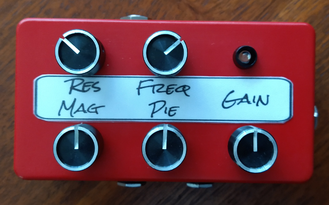
IMG_0611.png


Input is on TRS and magnetic pickup then goes to output jack and on to a v4 pedal and any Mag-only EFX. Pedal output returns to the blend and gain stages. Piezo pickup on resonator routes to its own standalone LPF, then to blend and gain. Mixed signal leaves on a TS jack, done. I like this a lot more than just having a straight buffer on the Pie side, although that does sound quite good too.
 
Nice looking work, Sanj.

Like JimC, I also find the in/out switch really useful to set eq and leave it on after. I now appreciate that the v4 pedal layout surrounds the two switches with knobs, which is protective.

Thanks very much, Charlie, for sharing the "Non-inverting gain stage/buffer" circuit called "Simple Gain" in the SHARE section of OSH Park. author: PW3B-LPF-OS

OSH Park ~ Shared Projects.

Without being able to see the traces from the OSH park art, here's my WAG on the parts values:

Re version control, NOTE THESE ARE NOT CORRECT PART VALUES, BUT ME JOKING AROUND.

R1 ?
R2 ?
R3 30K
R4 ?
R5 270R
R6 330K
R7 30K
R8 30K

C1 1.u
C2 1.u
C3 1.u
C4 ? .01
C5 47u
C6 22u

U1 OP1641

Thanks
 
Last edited:
  • Like
Reactions: Sanj and Passinwind
Nice looking work, Sanj.

Like JimC, I also find the in/out switch really useful to set eq and leave it on after. I now appreciate that the v4 pedal layout surrounds the two switches with knobs, which is protective.

Thanks very much, Charlie, for sharing the "Non-inverting gain stage/buffer" circuit called "Simple Gain" in the SHARE section of OSH Park. OSH Park ~ Shared Projects.

Without being able to see the traces from the OSH park art, here's my WAG on the parts values:

Re version control, NOTE THESE ARE NOT CORRECT PART VALUES, BUT ME JOKING AROUND.

R1 ?
R2 ?
R3 30K
R4 ?
R5 270R
R6 330K
R7 30K
R8 30K

C1 1.u
C2 1.u
C3 1.u
C4 ? .01
C5 47u
C6 22u

U1 OP1641

Thanks

LOL, I have no idea what the reference numbers even are on that one. But I could build one without looking at a schematic no sweat…;)
 
@Passinwind , an update. Upon retrieving it from my drummer's house, I realized my preamp has stereo outputs, so I decided it would be easier to design a modified PCB with the needed changes for bipolar power supplies. I also took advantage of this decision to learn KiCad -- what a refreshing difference from Eagle 7! I'd forgotten how much I enjoy doing board layouts.

Am I correct in thinking the first stage of the HPF is just an input buffer with a wee bit of gain?
 
@Passinwind , an update. Upon retrieving it from my drummer's house, I realized my preamp has stereo outputs, so I decided it would be easier to design a modified PCB with the needed changes for bipolar power supplies. I also took advantage of this decision to learn KiCad -- what a refreshing difference from Eagle 7! I'd forgotten how much I enjoy doing board layouts.

Am I correct in thinking the first stage of the HPF is just an input buffer with a wee bit of gain?

Yep, going with that format makes for a few more fine tuning options on the frequency rolloffs at either end. KiCAD has really improved over the last few years, thanks to some industry sugar daddies stepping up with cash infusions.
 
  • Like
Reactions: Andyman001 and Sanj
I'm using KiCad 6.0, as that's how long ago I installed it -- any pros/cons to upgrading?

If you upgrade it may herk up the library system if you roll your own footprints, as I often do. Not too hard to recover from, but a bit tedious. It probably would’ve gone easier if I had been more proactive on archiving things as I went on older designs.
 
  • Like
Reactions: Andyman001 and Sanj
I've only created a few so far, so that won't be too cumbersome.


Will changing it to unity gain cause any issues?

Thanks for all of your help.

As usual, it just depends. I’ve seen straight up followers with the opamp ouput shorted to the inverting input in quite a few reputable MI input circuits, but somewhere along the way I had better results with at least a small value feedback resistor and a compensating one on the input. Here’s a start on the subject: What is the purpose of a resistor in the feedback path of a unity gain buffer?

And then there’s gain staging, which is pretty much an unending rabbit hole!
 
Last edited:
  • Like
Reactions: Andyman001 and Sanj
"somewhere along the way I had better results with at least a small value feedback resistor and a compensating one on the input."

I understand the entry stage of the Passinwind HPF to be good for both active or passive sources and you've used 2K49 for the input and for the feedback resistors there. Is that the sort of "small value" you've seen work well?
 
  • Like
Reactions: Passinwind
"somewhere along the way I had better results with at least a small value feedback resistor and a compensating one on the input."

I understand the entry stage of the Passinwind HPF to be good for both active or passive sources and you've used 2K49 for the input and for the feedback resistors there. Is that the sort of "small value" you've seen work well?

Yep, 2k-3.6k has been my go-to, and then I tailor gain to taste with the other resistor off the inverting input. In my DIY amps I sometimes do an input impedance switch and go as low as ~18k for the low input shunt value, which works very well with my active basses, FWIW.
 
Take two on a blend pedal for my dobro/banjo mutant:

View attachment 5248544


Input is on TRS and magnetic pickup then goes to output jack and on to a v4 pedal and any Mag-only EFX. Pedal output returns to the blend and gain stages. Piezo pickup on resonator routes to its own standalone LPF, then to blend and gain. Mixed signal leaves on a TS jack, done. I like this a lot more than just having a straight buffer on the Pie side, although that does sound quite good too.

And now in process, an integrated version incorporating the MagPie circuitry and a v4 build into one 1590XX box:


DojoMojo.png


There are still several loose ends I need to clean up on the v4 Github repository, mainly the various pot, switch, and I/O connector options. Shipping from Tayda to the US took a very steep price hit recently, so I'll need to work up BOMs for US vendors for everything now.
 
Lookin' Good!
Can't wait to see this in the 1590-"flesh".
Maybe this Double-X beast will get rid of my Radial, F-Deck, etc...

I'm hoping to be able to fit a DI output in there too, FWIW. It'll probably be a few weeks, Amplifyfun is way backed up right now.
 
I'm hoping to be able to fit a DI output in there too, FWIW. It'll probably be a few weeks, Amplifyfun is way backed up right now.
This is EXACTLY what my friend Paul would want for his setup. He asked if it were possible to add a DI as he plays out a LOT and most venues require him to provide that output. He has been waiting patiently, so a few weeks more is no big deal. Thanks for adding this very necessary component.
 
This is EXACTLY what my friend Paul would want for his setup. He asked if it were possible to add a DI as he plays out a LOT and most venues require him to provide that output. He has been waiting patiently, so a few weeks more is no big deal. Thanks for adding this very necessary component.

Bear in mind that the 1590XX enclosure in post #1412 is quite a bit bigger than the 1590BBS that v4 is meant for. Something may have to give to fit a Jensen DI transformer in a stock v4 build, but I'll take a look at the one 1590BBS build I have on hand and see if we could make it work. We can probably expect going this route to double total cost, more or less. Looks like the JT-DB-E is running right around a hundred bucks from the usual distributor suspects now, and Jensen doesn't seem to be selling single pieces directly to end users as they used to. An active solution would be much cheaper, but I just don't have 100 hours to throw at doing it to my standards right now.
 
An active solution would be much cheaper, but I just don't have 100 hours to throw at doing it to my standards right now.
I was wondering why no one makes a solid-state DI as transformer technology is fine, but a bit old-school these days. I would be glad to do some research and design for a solid-state DI solution. I know the output parameters already. Is there anything special I need to know re the input parameters?
 
  • Like
Reactions: DJ Bebop
I was wondering why no one makes a solid-state DI as transformer technology is fine, but a bit old-school these days. I would be glad to do some research and design for a solid-state DI solution. I know the output parameters already. Is there anything special I need to know re the input parameters?

Lots of amps feature solid state ones, one mission critical design consideration is to make sure phantom power can't hurt it. Schematics for reasonably contemporary G-Ks, Traynors, etc. are readily available, but will probably need to be ported to a single supply format.
 
  • Like
Reactions: seanm