

Enjoy the benefits of a premium membership!
Upgrade Account
-
TalkBass has been independent since 1998. Add your voice.
Create a free account to reply to discussions, view embedded media, and browse with fewer display ads.
Join free Log in
Want zero display ads or expanded classifieds tools? Compare plans.
You are using an out of date browser. It may not display this or other websites correctly.
You should upgrade or use an alternative browser.
You should upgrade or use an alternative browser.
The Rickenbarner - my first fully scratch-build!
- Thread starter RaniBrandt
- Start date
More options
Who Replied?
Why is there a ground lug on the switch? Doesn't that just switch the hots off of the pickups? And then why would the second lead off of that same center connector go to the center connector of one of the pots? and one of the legs of that pot going to ground? This doesn't make sense to me.
I think you're seeing the right lug on the bottom row and visually combining it with the middle one on the top. The top row is pickup hot and cap to tone pot, then ground, then pickup hot and cap to tone pot, and the bottom are the two hot leads to the volume pots.


There are 5 lugs on the switch. The center is a ground, and only needs ONE lead going to the back of a pot, or to a point where a pot lug has been grounded. All tone controls should have the center lug grounded to the pot. This should be done with a piece of wire by a novice as getting solder inside the hole while trying to solder the lug there is a BAD thing. All tone controls (when orientated with lugs to the right) should have the TOP lug grounded to the case. The center lug on tone controls should have a wire going to a switch terminal CLOSEST to the guard. Tone caps should be soldered to a switch lug FARTHEST from the guard. The other lead on tone caps should be soldered to the upper lug on the tone cap when orientated with lugs to the right. I see these rules being violated all over this wiring. Wait a minute...I see what appear to be volume controls on the BOTTOM in this wiring...and a green chicklett cap. If that's the .0047 vintage tone cap, I leave them out except when restoring vintage wiring, or being combined with a push-pull pot to bypass it when necessary.
Last edited:
There are 5 lugs on the switch. The center is a ground, and only needs ONE lead going to the back of a pot, or to a point where a pot lug has been grounded. All tone controls should have the center lug grounded to the pot. This should be done with a piece of wire by a novice as getting solder inside the hole while trying to solder the lug there is a BAD thing. All tone controls (when orientated with lugs to the right) should have the TOP lug grounded to the case. The center lug on tone controls should have a wire going to a switch terminal CLOSEST to the guard. Tone caps should be soldered to a switch lug FARTHEST from the guard. The other lead on tone caps should be soldered to the upper lug on the tone cap when orientated with lugs to the right. I see these rules being violated all over this wiring.
This is starting to break my brain, but I'm going to try to suss this out now. There are some discrepancies between what you're saying here and the drawing you sent me.
1. The center lug of the switch has one lead, going to the back of the bass volume pot. Check.
2. Both tone controls have a ground wire from the center lug to the back of the pot. There is also a wire going from one tone center lug to the other, as per the drawing you sent me. Check.
3. Here's where what you're saying here differs from the drawing you gave me. According to the drawing, the TOP lugs of the tone controls (when lugs are pointed to the right) are where the caps are connected to the switch lugs. The center tone lugs are wired to the back of the pot (as you wrote here). The bottom tone lugs are open.
4. Also, the switch terminals closest to the guard, again, according to the drawing, go to the center lugs on the volume controls, one with a .0047 cap.
Wait a minute...I see what appear to be volume controls on the BOTTOM in this wiring...and a green chicklett cap. If that's the .0047 vintage tone cap, I leave them out except when restoring vintage wiring, or being combined with a push-pull pot to bypass it when necessary.
Yeah, I guess you missed when I said that I switched the volume and tone pot positions, so that the volumes would be on the top when playing. I just like it better that way, as that's what I'm used to on my other basses.
As for the chicklet, that's a .047 that I had to use to replace the one that I burned with the side of the soldering iron. Whoops! I do have a .0047 in there though, because it was there in the drawing you sent me. I don't see how that would cause the no-sound-but-buzzing issue, but I'll remove it and put in a straight lead and see what happens.
Any other thoughts? Anyone? I'm dying over here! I'm leaving for a week tomorrow, and I really wanted to get this thing done before then, as I have to finish building my shed when I get back!

- Apr 18, 2008
- 16,003
- 1
- 31,694
- Disclosures
- I'm highly opinionated and extremely self-assured
If you have time, you might try progressing in steps:
1. One pickup straight to jack - check for sound
2. One pickup to switch then straight to jack - check for sound
3. One pickup to switch then to volume pot then to jack - check for sound
4. One pickup to switch then to volume pot with tone pot then to jack - check for sound
5. Repeat 1-4 for the other pickup
It's lots of work, but it's a very methodical way to troubleshoot.
1. One pickup straight to jack - check for sound
2. One pickup to switch then straight to jack - check for sound
3. One pickup to switch then to volume pot then to jack - check for sound
4. One pickup to switch then to volume pot with tone pot then to jack - check for sound
5. Repeat 1-4 for the other pickup
It's lots of work, but it's a very methodical way to troubleshoot.
A partial schematic directly from the Rickenbacker website. There is no wire from the switch going to ground. And it's only showing 4 lugs coming off the switch. I'm confused.
2 inputs, one from each pickup, and 2 outputs, one from each pickup. No ground to or from the switch.
OK, I stand corrected. That center lug on the top row of lugs on the switch does go to ground. I found a spare Ric wiring harness in my parts drawer. And yes, it has 5 lugs. No one knows what it's for, and it's not showing on the schematic. And this harness only has one pickup wired in. The other pickup is installed in my Mapleglo.

Anybody out there got a standard current manufacture 4003 they are willing to pop open and photograph the living sh** out of? This is like a nest of snakes. The Ric schematic is known to be wrong (even if I could read the damn thing!), a deliberate obfuscation by the nefarious John Hall! 
Seriously, I can't think of another wiring layout that's impossible to find an accurate drawing for. Go Ric!
Seriously, I can't think of another wiring layout that's impossible to find an accurate drawing for. Go Ric!
Okay, so I made an output jack with two jumper wires on it and checked some things. The pickups both work. The connection to the end of the caps at the tone controls both work. The connection at the center lug (input) of the volume controls both work. The connection to the output lugs of the volume controls do NOT work. Does this mean that somehow BOTH of my volume pots are fried, or are they wired incorrectly?
JACKPOT! They were wired in reverse! Switched ground and output lugs, and presto!

I think my brain is going to break now. The drawings I sent you, while accurate, and the basis for a lot of what I do, require some amount of interpretation I suppose. This would be much easier to diagnose in person, but that's not possible. I do generally leave out the .0047 bass cut cap on the bridge pickup because it cuts the bass and volume out, particularly on older pickups. It is useful when you run both pickups together to balance out the sound, and I like it bypassed when soloing the bridge pickup. I don't think it's a problem here as long as the leads are insulated. For some really clear pics of RIC harnesses, go to my EBay auctions and take a close look. I shoot both the front and back of my harnesses, showing good detail. My screen name there is Aceonbass3. The current stock harnesses from RIC look like a bowl of red and green spaghetti.
Last edited:
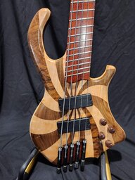


THANK YOU THANK YOU THANK YOU to everyone who helped me figure this out, especially Aceonbass, who went above and beyond, even though I'm sure I was annoying as hell!
The Rickenbarner lives! Thanks Aceon, from the Noob contingent. I'm still going to try to draw up a diagram for the next poor sap (me), based on Aceons's photos on eBay. I started a thread in Pickups and Electronics if anybody feels like taunting me.


