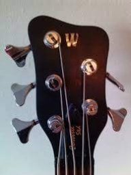
Thanks man! I really couldn't be happier with how it came together..That edge carving and scroll turned out really nice!
Now to get it to work...

TalkBass has been independent since 1998. Add your voice.
Create a free account to reply to discussions, view embedded media, and browse with fewer display ads.
Join free Log in
Want zero display ads or expanded classifieds tools? Compare plans.
Thanks man! I really couldn't be happier with how it came together..That edge carving and scroll turned out really nice!

Just brainstorming here... Are the little metal tabs along the edges of the the two sliders maybe causing some kind of short to ground or something?The braided cable goes to the output jack. The white (and gray and black) wires are from the pickup.
My next thought was to unsolder this, and test directly from pickup to jack. Then add back in the volume control, lastly add back the tone circuit.
At this point I am not certain that any of this works...

Have I mentioned how much I loathe wiring...
I think everything is connected properly. But I am getting nothing.
I used the 500k pots for both tone and volume. I followed this diagram.
P-Bass Wiring Diagram - Fralin Pickups
I know the jack is wired up correctly. Ground to chassis and pin 3 on the volume. Hot to pin 2 on the volume control.
The capacitor (4.7uf) is wired between pin 1 and chassis ground on the tone slider. Pin 3 of the tone control is not connected.
The pickup is wired hot to pin 1 on the volume, pin 2 of the tone is jumpered off pin 1 of the volume.
Both pickup grounds are tied to chassis ground.
View attachment 5143596
The braided cable goes to the output jack. The white (and gray and black) wires are from the pickup.
My next thought was to unsolder this, and test directly from pickup to jack. Then add back in the volume control, lastly add back the tone circuit.
At this point I am not certain that any of this works...
Most Nordstrand pickups have an extra ground wire for the poles, I think.I see. Why are there three wires from the pickup? Normally a P-pickup setup have two wires per pickup but two of those wires should go between the pickups. Only two wires should go to the control setup.
There is something weird going on where the shielding braid to the jack terminates. Judging by the picture the leg to the "hot side" of the cap goes underneath this ground point. Could this leg be touching something? That area looks really tight.
Most Nordstrand pickups have an extra ground wire for the poles, I think.


I was not aware of this. Looks like that part is wired correctly then.
I *think* the culprit is <drumroll> the mounting screws for the sliders. I had one un mounted, and it worked just fine, but once I mounted it, it stopped working properly. Frustrating.
I now need to shorten some 2MM screws... they need to be long enough to *just* go through the threaded part on top of the slider... hooray!
Unfortunately, no. So there's something critical in the screw path. Good thing I bought spares..Does it work again once you un-mount it? I am wondering if somehow a screw caused a short, or overtightening cracked something....
That's not the worst outcome, not by a long shot. Troubleshooting and creative problem solving are always a part of projects like this, it's part of what I like about itI *think* the culprit is <drumroll> the mounting screws for the sliders. I had one un mounted, and it worked just fine, but once I mounted it, it stopped working properly. Frustrating.
I now need to shorten some 2MM screws... they need to be long enough to *just* go through the threaded part on top of the slider... hooray!


Unfortunately, no. So there's something critical in the screw path. Good thing I bought spares..
Who designed these things?
I believe it will continue to amber, and the walnut will darken with age.I really like the way the color came out on the new one. Will that amber even more as it ages?