Calling out to effects and electronics gurus, 
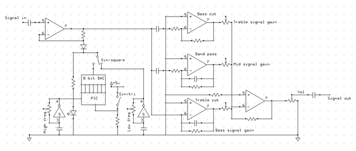
I have been thinking about making a tremolo pedal of my own design (with my knowledge from AS level electronics) and have come up with a possible circuit for it.
The basics for my idea so far are this:
Multiple chopping waveforms (square/triangle/sine)
The chopping wave forms will be generated through a PIC, digital to analogue converter and high/low freq relaxation oscillator.
The PIC will be wired up to increment and output a binary number every time the high frequency oscillator pulses. The DAC will take that binary number and convert it in to an analogue voltage that will control the feedback voltage on the op-amp.
I will use these outputs to (hopefully) modulate the gain of the pre amp in order to create the chop effect.
The output from the pre amp is then fed in to 3 cut filters (treble, bass, bandpass) which are then fed into a summing amplifier with a variable gain for each channel, in effect creating the ability to boost frequencies if I want (I will add in a bypass for this).
The circuit diagram is below.
Any comments/suggestions/errors that you have on it will be appreciated.
Thanks,
Tom
I have been thinking about making a tremolo pedal of my own design (with my knowledge from AS level electronics) and have come up with a possible circuit for it.
The basics for my idea so far are this:
Multiple chopping waveforms (square/triangle/sine)
The chopping wave forms will be generated through a PIC, digital to analogue converter and high/low freq relaxation oscillator.
The PIC will be wired up to increment and output a binary number every time the high frequency oscillator pulses. The DAC will take that binary number and convert it in to an analogue voltage that will control the feedback voltage on the op-amp.
I will use these outputs to (hopefully) modulate the gain of the pre amp in order to create the chop effect.
The output from the pre amp is then fed in to 3 cut filters (treble, bass, bandpass) which are then fed into a summing amplifier with a variable gain for each channel, in effect creating the ability to boost frequencies if I want (I will add in a bypass for this).
The circuit diagram is below.
Any comments/suggestions/errors that you have on it will be appreciated.
Thanks,
Tom