
• TalkBass has been independent since 1998. Add your voice.
    Create a free account to reply to discussions, view embedded media, and browse with fewer display ads.
    Join freeLog in
    Want zero display ads or expanded classifieds tools? Compare plans.

Warwick push pull replacement

I purchased an mec push pull pot for my 90s Warwick corvette. I got my friend to replace it but it didn't work so he put back in the old one for your moment. I'm wondering why there was more pins on the knew pot? Also why it didn't work? Here's some pics.

IMG_20190607_084321137.jpg
IMG_20190607_085603639.jpg
IMG_20190607_084321137.jpg
Screenshot_20190607-084655~2.png
 

Attachments

  • MVIMG_20190615_173704877.jpg
    MVIMG_20190615_173704877.jpg
    2 MB · Views: 122
  • Screenshot_20190618-220302.png
    Screenshot_20190618-220302.png
    1.4 MB · Views: 119
  • IMG_20190612_203334406.jpg
    IMG_20190612_203334406.jpg
    681.1 KB · Views: 118
  • IMG_20190607_084344299.jpg
    IMG_20190607_084344299.jpg
    205.6 KB · Views: 108
  • IMG_20190607_084329655.jpg
    IMG_20190607_084329655.jpg
    132.2 KB · Views: 111
  • Screenshot_20190618-220302.png
    Screenshot_20190618-220302.png
    1.4 MB · Views: 119
  • Screenshot_20190618-220302.png
    Screenshot_20190618-220302.png
    1.4 MB · Views: 121
  • Screenshot_20190607-084616.png
    Screenshot_20190607-084616.png
    200.6 KB · Views: 124
If you didn't know, MEC is a branch of Warwick. These pots are made to match how the circuitry is laid out in the pcb, which is real squirrelly to figure out in something as proprietary as active Wariwicks. It's not hard to imagine they've changed what's happening inside the pots and circuit boards in the last twenty-five years. It could well be easier/cheaper to replace the whole system than chase down the components you need. A different pin arrangement is a pretty big hint that a component will not be compatible. I would contact Warwick to get info on what pot you need, and if your bass will even do what you want it to. Good luck!
 
From that last pic, it looks like this is a (non-true) bypass switch on the volume control. I'm guessing it's a single sided board and really, you could wire this just fine without the board.

Also why it didn't work? Here's some pics.
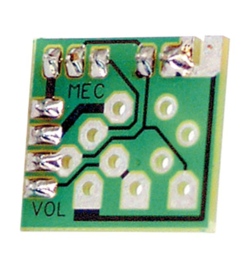
The photo is not super clear, but it looks like a solder bridge or two, and a dry/incomplete solder joint.

Notice the bottom right-hand hole is for the anti-clockwise lug of the pot. This should be earth. (Notice the trace from here goes to four other holes.) I'm guessing the green wire at the top RH corner is the signal from the blend pot because it goes to the clockwise lug of the vol pot. There looks to be a solder bridge across to the land directly to its left. As I mentioned, this is earth, so a bridge here would mute the signal.

The other possible solder bridge looks like a shiny circle near the lower left corner. The second wire from the bottom on the left edge of the board is earth. If this shiny dot of solder is connecting this land to either the middle or clockwise lugs of the vol pot, this would also mute the signal.

The incomplete joint is fairly obvious. In fact you can see down into the hole. This the lower of the switch contacts, and is connected to the middle pot lug and the lower left wire (which should go to the input of the pre). This would effect the operation of the "pull" side of the switch.
 
From that last pic, it looks like this is a (non-true) bypass switch on the volume control. I'm guessing it's a single sided board and really, you could wire this just fine without the board.


The photo is not super clear, but it looks like a solder bridge or two, and a dry/incomplete solder joint.

Notice the bottom right-hand hole is for the anti-clockwise lug of the pot. This should be earth. (Notice the trace from here goes to four other holes.) I'm guessing the green wire at the top RH corner is the signal from the blend pot because it goes to the clockwise lug of the vol pot. There looks to be a solder bridge across to the land directly to its left. As I mentioned, this is earth, so a bridge here would mute the signal.

The other possible solder bridge looks like a shiny circle near the lower left corner. The second wire from the bottom on the left edge of the board is earth. If this shiny dot of solder is connecting this land to either the middle or clockwise lugs of the vol pot, this would also mute the signal.

The incomplete joint is fairly obvious. In fact you can see down into the hole. This the lower of the switch contacts, and is connected to the middle pot lug and the lower left wire (which should go to the input of the pre). This would effect the operation of the "pull" side of the switch.
Really appreciate your reply i should have stated that this pic is of the old pot connected to the pcb board. It works fine but now and again it starts making noise like a dirty pot. If i give the pot a hard tap it works fine again. I've tried cleaning pot. This helped for a short time but then went back to the way it was.
 
the red lines pins do not have anywhere to go on pcb board. The blue doesn't either. But on the opposite side of where the blue pin is there is a pin on the old pot. Should i cut off the pins that don't fit and solder the blue pin to the other side of pcb board like old pot?
PhotoEditor_20190623_120712257.jpg
 

Attachments

  • PhotoEditor_20190623_120540431.jpg
    PhotoEditor_20190623_120540431.jpg
    264.8 KB · Views: 117
the red lines pins do not have anywhere to go on pcb board. The blue doesn't either.

You can cut these off. They are simply for mounting and/or shielding.

this pic is of the old pot connected to the pcb board

It came from the factory like this?!! That's not great soldering.

It works fine but now and again it starts making noise like a dirty pot. If i give the pot a hard tap it works fine again.

Yeah, that's probably that excess solder on the board and/or the dry joint. You need to get some solder wick and clean it up a bit then reflow the dodgy joints. Should be fine after this.
 
Everything? The other pots too?

Did you try and replace the pot at first like i did?

I did look into just replacing the one pot but I decided to just replace the whole preamp because it would be easier and the rest of the electronics are already 20 years old. Now I have a brand new preamp that I expect to get another 20 years out of and I kept my old preamp. So now if i have a problem with a pot I have replacements ready to go and won't have to order one from Warwick.
 
I did look into just replacing the one pot but I decided to just replace the whole preamp because it would be easier and the rest of the electronics are already 20 years old. Now I have a brand new preamp that I expect to get another 20 years out of and I kept my old preamp. So now if i have a problem with a pot I have replacements ready to go and won't have to order one from Warwick.
Ah ok. I look into that option if i can't get this pot to work.
Ps i i wouldn't rely on using the old pot as a replacement as you might run into the same problem as me if the pin out has changed. I've emailed Warwick. Hopefully ill get it sorted soon