
• TalkBass has been independent since 1998. Add your voice.
    Create a free account to reply to discussions, view embedded media, and browse with fewer display ads.
    Join freeLog in
    Want zero display ads or expanded classifieds tools? Compare plans.

Double Bass What pickup is this, and adhesive question

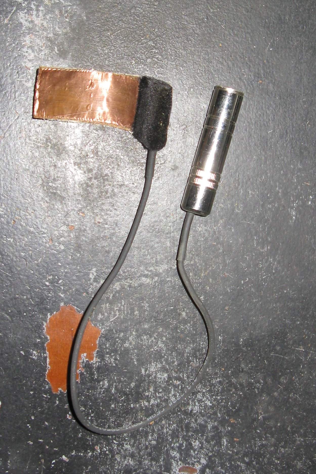
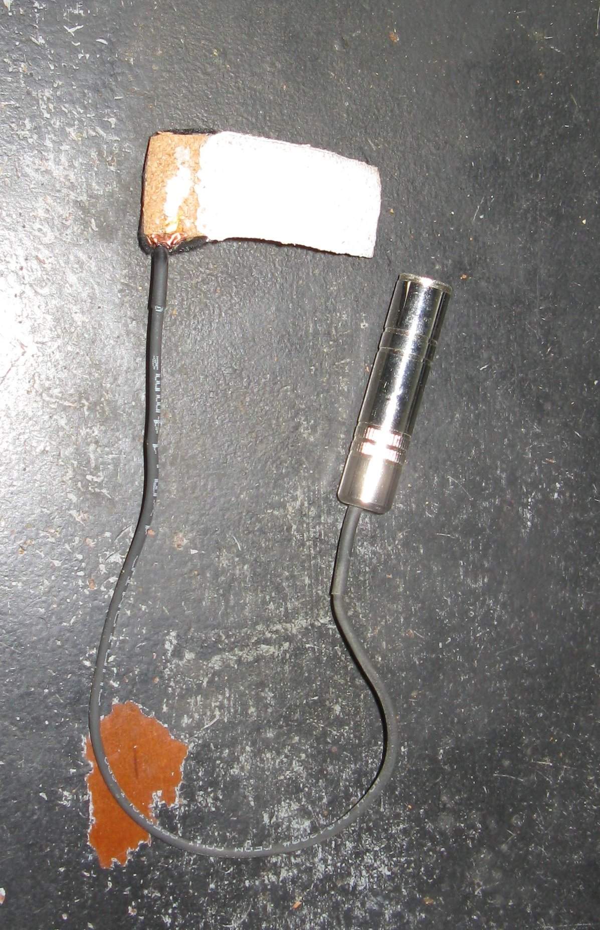
This pickup came on my 69 Kay, anyone know the make?

Also, I noticed when playing through this that there were feedback issues unless I taped or puttied down the black fuzzy part of the pickup (that's adjacent to the part under the bridge foot) to the top of the bass. The main piezo part was attached to the bass with some kind of white adhesive that came off clean and didn't damage the finish and is still very tacky. Anyone know what the stuff is, or know of something similar I could use on the side where there isn't any?
IMG_0415.JPG

IMG_0416.JPG
 

Attachments

  • IMG_0415.JPG
    IMG_0415.JPG
    338.8 KB · Views: 28
You might need an impedance buffer or preamp with several MegOhms input impedance.
As far as I remember the Measurement Specialities element (depending on area and thickness) can need up to 22 MegOhms, but I think 10 MegOhms should be enough for that one.
And I'm not sure if yours is made from a part of this manufacturer. There are a few others out too.
 
Realizing that the pickup is larger than the foot of the bridge I'm intending to shape for the bass. It fit the old bridge foot. Can I trim the piezo down?
Don't do that. The probability is very high that you ruin the pickup. At least you damage the proper shielding.

I do that with my own piezo disk based pickups, but then I know what I do and how and how to damage it if done wrong.
 
I need to correct myself.

It is not the measurement specialities one that I had in mind:
Link Removed

It looks more like the Shadow NFX element wrapped with copper foil. I was irritated by the copper foil, because the NFX is black piezo foil in clear plastic with the black plastic case attached to the smaller side. There is a FET in the black case where the cable emits that needs power, so if it is an NFX sensor, then the FET needs to be bridged (just a cable short) to work without a battery. In this case the output is rather low (it is with my powered NFX) and input impedance of the first amp stage should at least be 10 MegOhms.
 
I need to correct myself.

It is not the measurement specialities one that I had in mind:
Link Removed

It looks more like the Shadow NFX element wrapped with copper foil. I was irritated by the copper foil, because the NFX is black piezo foil in clear plastic with the black plastic case attached to the smaller side. There is a FET in the black case where the cable emits that needs power, so if it is an NFX sensor, then the FET needs to be bridged (just a cable short) to work without a battery. In this case the output is rather low (it is with my powered NFX) and input impedance of the first amp stage should at least be 10 MegOhms.

Interesting... it has worked fine in the past, though with a very low output. Are you saying that powering the fet with a battery (or phantom power?) would boost the signal?
 
I think nothing should come out if there is a FET in the signal path, but I'mmot an electronic specialist and never tried it that way myself.

I also never opened the black plastic case of an NFX pickup, only the battery adapter.

But since there is only one wire plus the ground shielding, the power and signal needs to share that wire. So there needs to be a resistor to the + of the battery and a capacitor to the signal output. The value of the capacitor is not that critical but the resistor value is and the battery voltage should be 3 volts if it is an NFX sensor.

I'm not at home, so I cannot measure the important component values of the battery adapter, but I might find some time for that next week.
So don't put any voltage in now.

Meanwhile you might want to study the schematics of simple impedance buffers like Francis Decks Quick'n'Dirty or the Mintbox which are easy to find on the Internet. There you can see how the power source is connected and how the audio signal gets decoupled.
 
I think nothing should come out if there is a FET in the signal path, but I'mmot an electronic specialist and never tried it that way myself.

I also never opened the black plastic case of an NFX pickup, only the battery adapter.

But since there is only one wire plus the ground shielding, the power and signal needs to share that wire. So there needs to be a resistor to the + of the battery and a capacitor to the signal output. The value of the capacitor is not that critical but the resistor value is and the battery voltage should be 3 volts if it is an NFX sensor.

I'm not at home, so I cannot measure the important component values of the battery adapter, but I might find some time for that next week.
So don't put any voltage in now.

Meanwhile you might want to study the schematics of simple impedance buffers like Francis Decks Quick'n'Dirty or the Mintbox which are easy to find on the Internet. There you can see how the power source is connected and how the audio signal gets decoupled.

... and then unbrokenchain spent half an hour wrapping his head around what DoubleMIDI was telling him in simple terms... haha thanks for your help!
 
Reinstalled the pickup after repair to the instrument. What should I use to adhere the lifted part to the top of the bass? For whatever reason it has feedback issues when it's sitting up like that, but when I tape it down to the top that problem disappears. Tape only holds for a set or two though and looks bad.


IMG_0436.JPG