• TalkBass has been independent since 1998. Add your voice.
    Create a free account to reply to discussions, view embedded media, and browse with fewer display ads.
    Join freeLog in
    Want zero display ads or expanded classifieds tools? Compare plans.

Winter Build Off 2020 - Sub-woofer On A Stick

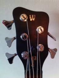
Here's the picture of the tear out on the FB
If anyone has any ideas of how to fix or hide that, let me know.
You want the router bit to be taking off the smallest amount possible. Start off with a rough cut as close to your final profile as possible (band saw it, etc), use a spiral router bit, and perform a climb-cut very carefully.

EDIT: Noticed your original question was how to fix it, not prevent it in the future, but I'll leave this up for others to address the prevention angle.
 
OK, here's the new unswerving plan of the day. I will abandon the idea of laying up the carbon fibre cloth over the white foam molds. I'm replacing the idea with the box-beam concept... The body will be built with panels. The front and back will be thin flat foam, laminated with fibre glass inside and carbon fibre outside. The outer sides and inner chambering will be constructed using some reclaimed wiggle board. When that is done, I will glass all of the body parts together.

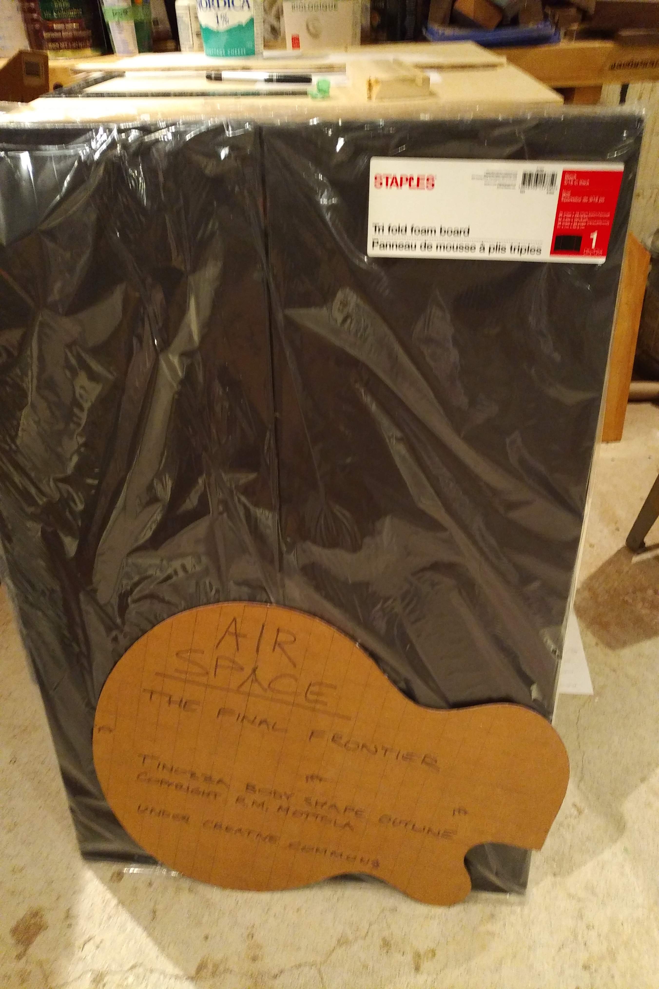
Here's the inappropriately named wood pile photo for the foam.

Wiggle board pix to follow when I dig them out of the scrap pile.

This weekend, I plan to laminate create two flat panels. I should get the glass on one side tonight and CF on the other side tomorrow. I hope to start constructing the innards on Sunday.
 
OK, here's the new unswerving plan of the day. I will abandon the idea of laying up the carbon fibre cloth over the white foam molds. I'm replacing the idea with the box-beam concept... The body will be built with panels. The front and back will be thin flat foam, laminated with fibre glass inside and carbon fibre outside. The outer sides and inner chambering will be constructed using some reclaimed wiggle board. When that is done, I will glass all of the body parts together.

Here's the inappropriately named wood pile photo for the foam.

Wiggle board pix to follow when I dig them out of the scrap pile.

This weekend, I plan to laminate create two flat panels. I should get the glass on one side tonight and CF on the other side tomorrow. I hope to start constructing the innards on Sunday.
I'm not gonna pretend that I'm not confused.....but I'm Really looking forward to seeing how it unfolds....:D:thumbsup:
 
It's both unconventional and something of an experiment, I'd wager, and I am definitely watching... ;)


OK, here's the new unswerving plan of the day. I will abandon the idea of laying up the carbon fibre cloth over the white foam molds. I'm replacing the idea with the box-beam concept... The body will be built with panels. The front and back will be thin flat foam, laminated with fibre glass inside and carbon fibre outside. The outer sides and inner chambering will be constructed using some reclaimed wiggle board. When that is done, I will glass all of the body parts together.

Here's the inappropriately named wood pile photo for the foam.

Wiggle board pix to follow when I dig them out of the scrap pile.

This weekend, I plan to laminate create two flat panels. I should get the glass on one side tonight and CF on the other side tomorrow. I hope to start constructing the innards on Sunday.
 
Let's see if I can reduce some confusion, at least by a little.

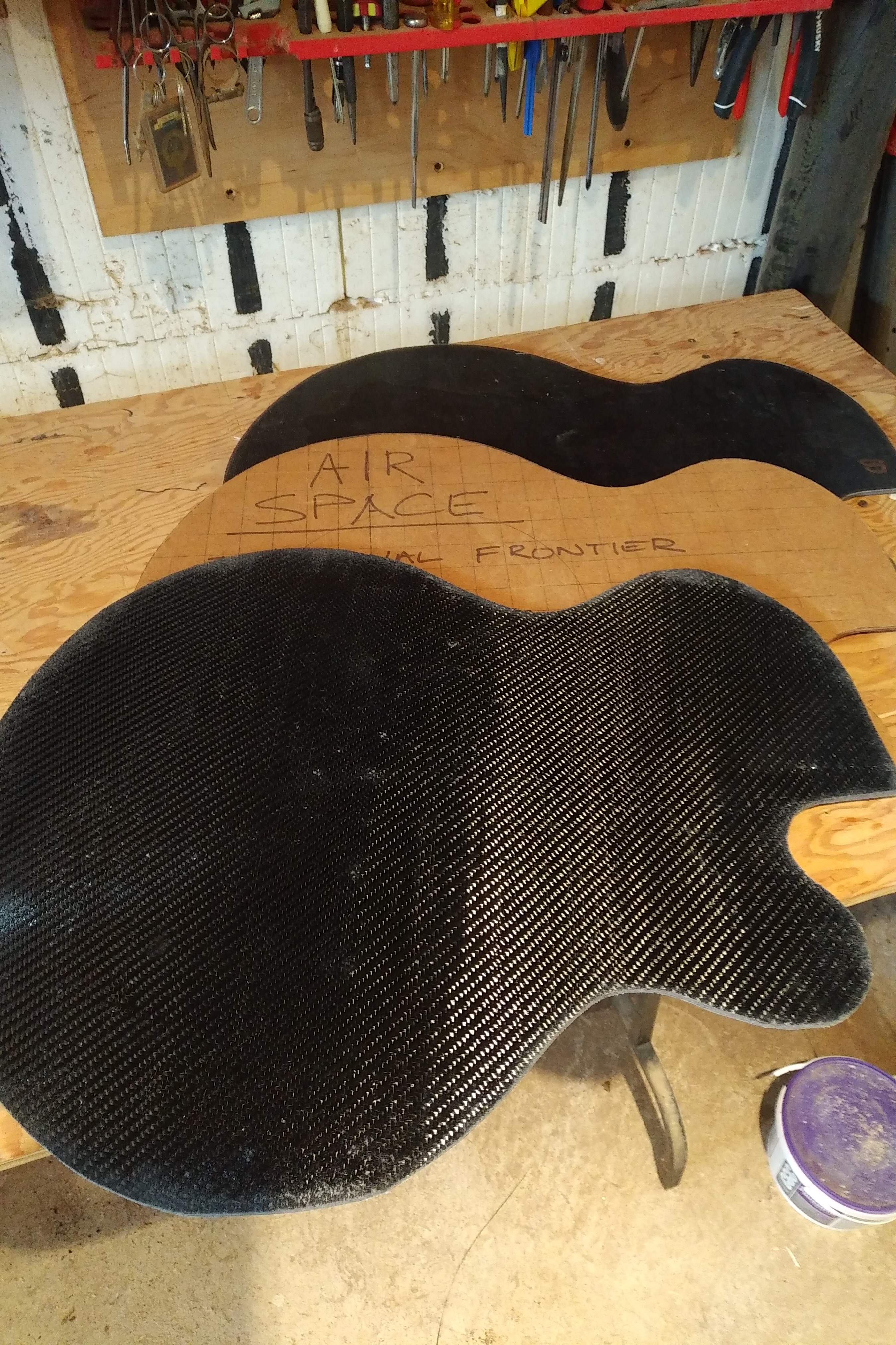
I glassed one side of the foam board and carbon fibred the other side, So far it is just a flat panel so a picture doesn't show much.

I dug the strips of wiggle board out of the scrap pile...

... and glued up the sound well for the resonator at the centre of the spiral duct. I made the ID of the sound well just over 9.5", so I can upgrade to a commercially available resonator cone if plan A doesn't sound very good. This will make some sections of the spiral duct a little narrow.

Next steps are to cut the top and bottom panels to shape and to start building the spiral and internal bracing.
 
I got some work done this morning because this afternoon will be dedicated to World Sock Disappearance Day - they day when all university students get taken back to campus and dads wonder where all their socks went.

The sound well is out of the clamps.
The 9.5" ID sound well takes up a lot of space. I want the duct to spiral twice around, but this would make the ducts quite narrow. Maybe I'll look for alternative resonator cone sizes and make a smaller sound well. It's no big deal until it gets mounted to the body panels.

Speaking of body panels...
These are jig sawed a little oversize and will be trimmed to the perimeter of the internal structure.

The foam seems to allow more "squish" than I'd like. I may make alternate panels using door skin plywood.

Sound well diameter, duct routing, panel core material... brace yourselves for more seat-of-the-pants decisions.
 
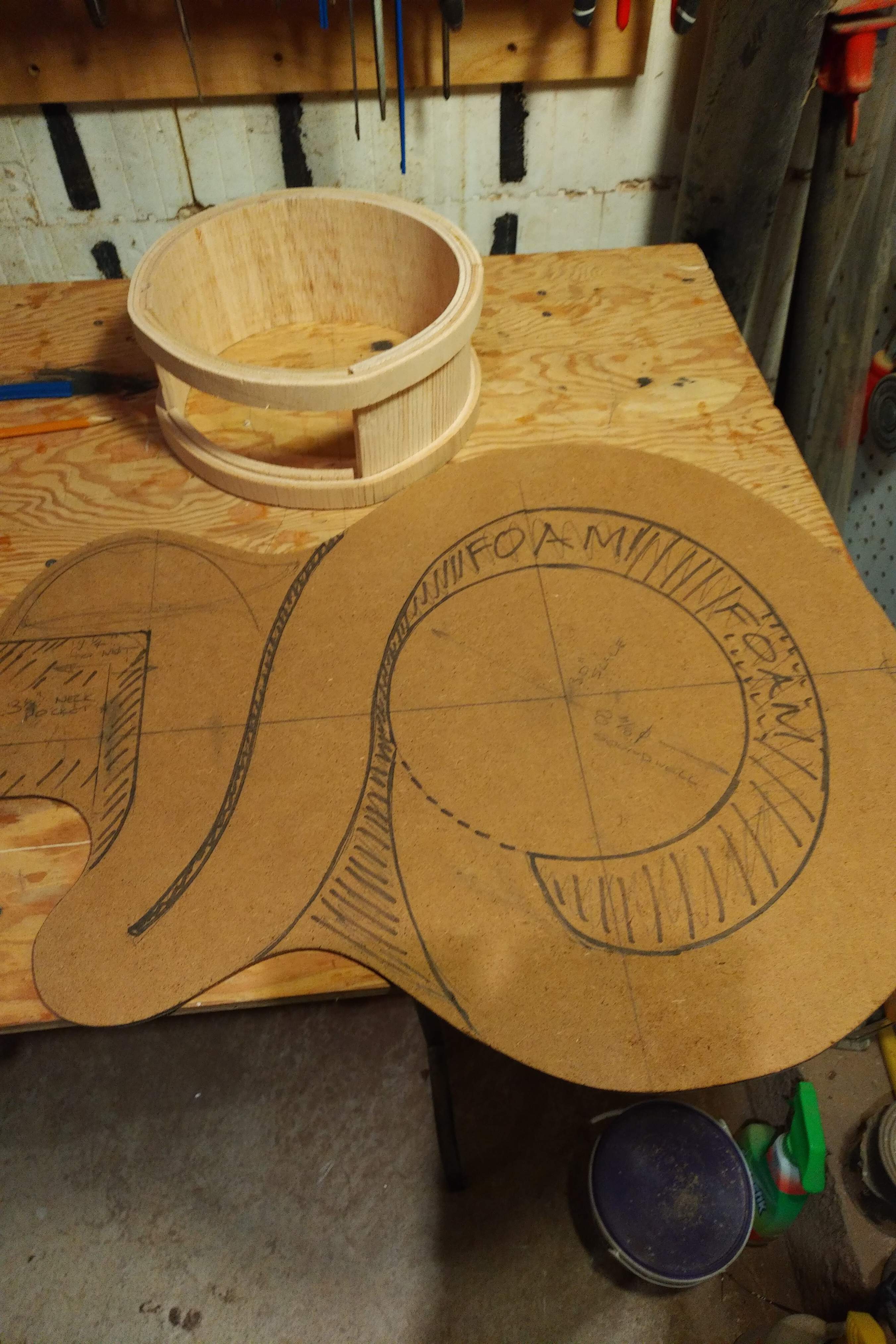
I've put more thought to the internal ducting and structure. The key design constraints are bridge position in the middle of the sound well and length of duct. With that in mind, I've settled on a smaller 8.25" sound well which does fit an off the shelf reso cone. and 60" duct length. This is what I have in mind - mirror image, NOT a leftie.
 
I've put more thought to the internal ducting and structure. The key design constraints are bridge position in the middle of the sound well and length of duct. With that in mind, I've settled on a smaller 8.25" sound well which does fit an off the shelf reso cone. and 60" duct length. This is what I have in mind - mirror image, NOT a leftie.
:jawdrop:
 
I've put more thought to the internal ducting and structure. The key design constraints are bridge position in the middle of the sound well and length of duct. With that in mind, I've settled on a smaller 8.25" sound well which does fit an off the shelf reso cone. and 60" duct length. This is what I have in mind - mirror image, NOT a leftie.
This thing is really starting to take shape :thumbsup:

Is the duct going to open up to a sound hole on the upper bout?
 
This looks like a fun experimental project! You are diving into the wild end of acoustic stringed instruments. We'll be entertained watching to see what you discover. Carry on brave Luthier!

A couple suggestions about the serpentine duct:

A big problem with a fixed-length acoustic duct like that is it will tend to form loud standing waves at one particular frequency. It'll exaggerate one really loud note. And it'll be hard to design it to be the exact note you want. You really won't know its resonant frequency for sure until you build it and test it.

And you really don't want the bass to be a one-note blast. That is, you don't want it to play the low A really loud, as compared to the other notes. What you want the back chamber and serpentine duct to do (I presume) is add some soft deep undertones in behind the mids and highs that will be coming off the front side of the resonator diaphragm. You want those undertones to be fairly even in volume as you play notes up and down the scale on the bass.

The way to do this is to make the serpentine duct more ambiguous; a less sharply defined length. If it were a piece of tubing, slice the end off at a steep angle. So the end is a long ellipse. That will bring down the volume of the resonant note, and spread it wider over the frequency range. Less of a single blast and more of a louder range of notes.

In your design, you can do this softening of the duct at either end, or at both. Inside the resonator drum, blend the duct in with a long gradual opening. A long elliptical port. And/or do the same thing at the outer end of the duct, where it exits the body in some kind of port.

About that exit port: The sound waves coming out of the end of the duct will be 180 degrees out of phase with the sound waves coming off the front side of the resonator diaphragm. If you make the exit port facing forward, fairly near the resonator, then the sound waves from the duct will be partially cancelling out and muting the low sounds from the front. You don't want to do that, I assume. Make the duct exit port come out the back of the body. That way, the air movement will be adding to and reinforcing the air movement coming from the front.

Also, don't line the serpentine duct with sound absorbing material. That's like putting a sock in the horn of a trumpet. Make the back chamber and duct work to add the extra sound that you want. Don't stick a sock in it unless it's horrible and hopeless.

For some real R & D fun:
Pull out one of your bass speaker cabinets, like a 1 x 15. Cut a piece of plywood to the size of the front of it. Find a 2" diameter x 60" long cardboard shipping tube. Bore a 2" hole in the middle of the plywood, and attach the shipping tube to it, sticking straight out. Strap the plywood to the cabinet. Now almost all of the sound will be driven out through the tube. Plug in a handy electric bass and start playing scales, listening to what you get out at the end of the tube. Find the resonant frequency by experimenting, and see how other notes nearby sound. This is a basic mockup of your serpentine duct, and a test of what happens when you drive sound through it.

Get out your box cutter and duct tape and play around with the length of the tube, and try cutting the angled end. You can even go crazy and mock up the whole resonator drum chamber and planned serpentine duct. Mount it to the plywood and use the electric bass and cabinet to drive sound through it. Really test it before you build the final version.

Go to it! This is the fun part of building basses!
 
@Bruce Johnson , you are hitting on a lot of the questions spinning around in the little hamster wheel in my head. From what I've read, the physics only takes you so far and then trial and error takes over. That's why there are as many contradictory rules of thumb as practical formulae.

The 60" length is 1/4 the wave length of low A. I've been lead to expect to boost the range of notes up or down half an octave from there. I won't really know until I build it. I hadn't thought of slicing the end of the duct - That's one more thing to test.

The sound absorbing material is intended to reduce standing waves. That sounds important. I'll have to test that too.

I'm going to have to think through the phasing. Does 1/4 wave, reflected back through the same duct double or cancel the wave? I could test having no opening, an opening on the front and an opening on the back to see which works.

Your "R&D Fun" section is probably the most brilliant thing in whole thread... TEST TEST TEST. I will be using a bolt-on neck, so I may just have to be willing to build and re-build a few bodies.
 
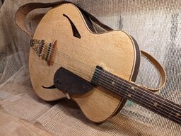
There happens to be a guitar on my local craigslist that I’m guessing may have inspired this idea. Is that the case or is it just coincidence? Awesome idea either way

upload_2020-1-9_17-6-33.jpeg
 
There happens to be a guitar on my local craigslist that I’m guessing may have inspired this idea. Is that the case or is it just coincidence? Awesome idea either way

View attachment 3661634
Partially. I really wanted the carbon fibre look, but to get through the experimentation, I'm going to compromise and work with cheaper materials. Consider that future scope.
 
  • Like
Reactions: Fat Freddy
I got some work done over the weekend. I built the spiral duct around the sound well and then trimmed the back panel flush to the rough sides on the router table


I put in a neck block, tail block and four other blocks so I can screw in the last panel leaving access to make changes to the inside. Having abandoned the cutaway, I could still change my mind of whether the open side is the back or the front. The current plan was to glue on another skin ply piece then wrap the whole thing in fibre glass or carbon fibre. But I do have some stainless steel sheet big enough to make a top. Either way, now I only want the top to vibrate over the sound well, but nowhere else.

Here is the other side (fibre glass over door skin ply)

I haven't forgotten that I need to get back to fixing the tear out on the neck some time soon.