

Enjoy the benefits of a premium membership!
Upgrade Account
-
TalkBass has been independent since 1998. Add your voice.
Create a free account to reply to discussions, view embedded media, and browse with fewer display ads.
Join free Log in
Want zero display ads or expanded classifieds tools? Compare plans.
You are using an out of date browser. It may not display this or other websites correctly.
You should upgrade or use an alternative browser.
You should upgrade or use an alternative browser.
Wiring Diagram for Custom G&L MFD Humbucker Setup
- Thread starter jaroh24
- Start date
More options
Who Replied?

Ok, so the original G&L schematic had a 250K volume pot with a 201K resistor. I'm assuming I should use this for reference and then adjust to taste... I was planning on using a 500K volume potYes, & I was wrong about the "resistor" on the volume pot. I believe it's a capacitor for what they call "treble bleed", which means you don't lose the highs when you roll back the volume.
Only thing is, I don't know what value they were going for.
View attachment 3168526
Yes, 500K Ohm, but ironically you might find it bright enough that you wish you'd installed a treble cut pot.
If you need to, you can install a treble cut on a concentric volume pot later.
relevant post about "treble bleeds":
Treble-Bleed circuit on bass?
alternatively, you could use the volume pot to cut some treble, if you did not install a "treble bleed" or a treble cut pot
BTW, I'm sure that 201K is not a resistor, look at the bass cut pot on the G&L drawing.
Those HAVE to be capacitors, or it wouldn't work.
Those are capacitor codes.
201 seems awfully low, however:
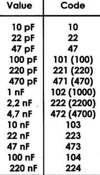
200 picoFarad
Wait, I think G&L have some something screwy here & indicated to add 1,000 to that code,
making it a 200 x 1,000 = 200 nanoFarads
If you need to, you can install a treble cut on a concentric volume pot later.
relevant post about "treble bleeds":
Treble-Bleed circuit on bass?
alternatively, you could use the volume pot to cut some treble, if you did not install a "treble bleed" or a treble cut pot
BTW, I'm sure that 201K is not a resistor, look at the bass cut pot on the G&L drawing.
Those HAVE to be capacitors, or it wouldn't work.
Those are capacitor codes.
201 seems awfully low, however:
200 picoFarad
Wait, I think G&L have some something screwy here & indicated to add 1,000 to that code,
making it a 200 x 1,000 = 200 nanoFarads
Last edited:
Hmmm weird they are using a code for the cap values...Yes, 500K Ohm, but ironically you might find it bright enough that you wish you'd installed a treble cut pot.
If you need to, you can install a treble cut on a concentric volume pot later.
relevant post about "treble bleeds":
Treble-Bleed circuit on bass?
alternatively, you could use the volume pot to cut some treble, if you did not install a "treble bleed" or a treble cut pot
BTW, I'm sure that 201K is not a resistor, look at the bass cut pot on the G&L drawing.
Those HAVE to be capacitors, or it wouldn't work.
Those are capacitor codes.
201 seems awfully low, however:
View attachment 3168547
200 picoFarad
Wait, I think G&L have some something screwy here & indicated to add 1,000 to that code,
making it a 200 x 1,000 = 200 nanoFarads
I also will mention that I plan to be using a Broughton HPF+LPF pedal on all the time with this bass. So I could set the LPF to be at 5000 Hz, and then have all high frequencies cut after that. I realize that because I don't have a tone bleed circuit installed, that I may have a +3 dB boost at around 5000 Hz or so, but again, the LPF would resolve most of that... Plus I wouldn't mind a tad bit of treble boost in the upper frequencies as long as it is not + 8 or 10 dB.
Do you think I would still need a treble bleed circuit with that LPF? If so, I will experiment with it. You have been very helpful so far. I am very thankful.
OTOH, that 200 nF seems too high. From the stuff I've seen online 1 nF is typical for this & RobbieK posted that it might be good to go higher.
So, if you want to install the "treble bleed", you might try a 2 nF first (in case G&L's math is just off, not to mention their drawing is confusing)
I think a 200 nF would pass too much of the signal & your Volume pot wouldn't function well for the first half of the sweep & 200 picoFarad is probably too small to hear a difference.
Maybe you're misunderstanding the "treble bleed", it's meant to keep the high frequencies in the signal, which is why I dislike the misnomer of it. (& use quotes around it)
If you'd prefer lowering the volume cuts highs, then don't install one.
So, if you want to install the "treble bleed", you might try a 2 nF first (in case G&L's math is just off, not to mention their drawing is confusing)
I think a 200 nF would pass too much of the signal & your Volume pot wouldn't function well for the first half of the sweep & 200 picoFarad is probably too small to hear a difference.
Maybe you're misunderstanding the "treble bleed", it's meant to keep the high frequencies in the signal, which is why I dislike the misnomer of it. (& use quotes around it)
If you'd prefer lowering the volume cuts highs, then don't install one.
Ah, now I see what you are saying. Ok well, in that case, I may need to add a 1nf cap. I prefer my signal to be relatively flat up until 5000 Hz or so. I don't typically need or care about frequencies above 5000 Hz since I don't use a tweeter on my cab.OTOH, that 200 nF seems too high. From the stuff I've seen online 1 nF is typical for this & RobbieK posted that it might be good to go higher.
So, if you want to install the "treble bleed", you might try a 2 nF first (in case G&L's math is just off, not to mention their drawing is confusing)
I think a 200 nF would pass too much of the signal & your Volume pot wouldn't function well for the first half of the sweep & 200 picoFarad is probably too small to hear a difference.
Maybe you're misunderstanding the "treble bleed", it's meant to keep the high frequencies in the signal, which is why I dislike the misnomer of it. (& use quotes around it)
If you'd prefer lowering the volume cuts highs, then don't install one.
I'm assuming the treble is flat until you begin to lower the volume knob? Since MFDs are hot pickups, I will be adjusting the volume pot to taste, and will have to add that "treble bleed" cap.
I also just realized that G&L might have just reversed the code on accident... The drawing says 201K, but maybe they meant 102K which is equal to 1 nf. That is what you're saying is the most common value for these circuits.OTOH, that 200 nF seems too high. From the stuff I've seen online 1 nF is typical for this & RobbieK posted that it might be good to go higher.
So, if you want to install the "treble bleed", you might try a 2 nF first (in case G&L's math is just off, not to mention their drawing is confusing)
I think a 200 nF would pass too much of the signal & your Volume pot wouldn't function well for the first half of the sweep & 200 picoFarad is probably too small to hear a difference.
Maybe you're misunderstanding the "treble bleed", it's meant to keep the high frequencies in the signal, which is why I dislike the misnomer of it. (& use quotes around it)
If you'd prefer lowering the volume cuts highs, then don't install one.
EDIT: nevermind that can't be the case. I just looked at least 8 different diagrams by G&L that all had the volume knob being a 250K pot with a 201K cap wired in parallel...
All the diagrams I looked at were found here:
G&L Wiring Diagrams and Schematics
Last edited:
If you don't have a tone control (which makes some sense here, since the two switches already open up a wide variety of tones), you could use your volume control as a tone control of sorts (assuming you don't use the treble bleed cap); turning it down slightly will allow some highs to escape to ground. Could be a handy feature...
Another thing G&L has done on some basses is drop the pickups' resonant frequency by putting a .001 uF capacitor in parallel with the volume pot's input. So if the pickups have too much of a high frequency spike for your taste, that can tame them a bit (along with the 250K volume pot).
Another thing G&L has done on some basses is drop the pickups' resonant frequency by putting a .001 uF capacitor in parallel with the volume pot's input. So if the pickups have too much of a high frequency spike for your taste, that can tame them a bit (along with the 250K volume pot).
I posted something similar earlier, but it was shrouded in text:
alternatively, you could use the volume pot to cut some treble, if you did not install a "treble bleed" or a treble cut pot
Good to know. If there is too much of a resonant frequency, I will try soldering a cap on the volume pot to reduce it some. I also have a LPF pedal that I could use to cut off any unnecessary high frequencies.If you don't have a tone control (which makes some sense here, since the two switches already open up a wide variety of tones), you could use your volume control as a tone control of sorts (assuming you don't use the treble bleed cap); turning it down slightly will allow some highs to escape to ground. Could be a handy feature...
Another thing G&L has done on some basses is drop the pickups' resonant frequency by putting a .001 uF capacitor in parallel with the volume pot's input. So if the pickups have too much of a high frequency spike for your taste, that can tame them a bit (along with the 250K volume pot).
By the way, I learned that some of the previous wiring diagrams that were posted are not correct. If you are using the MFD pickups that are sold on the G&L site, they are not wired with "k-wiring" and must be wired according to the Daveplaysbass specs if you are wanting a series/parallel/single coil switch. Down below I will post the corrected circuits for just a single pickup, though this can be done with 2 pickups as well.

This shows one pickup with the ability to switch between series/parallel/single coil wirings. It also has a volume knob and a tone knob with a 1nF loading cap to reduce the large resonant peak from MFD pickups (this is in the stock G&L wiring sheets). It also has a tone knob and a volume knob just like a p-bass, though the tone knob is before the volume knob (which is a good idea if you don't want the volume knob to affect the tone knob response).

I always leave my tone knob wide open and prefer to change the treble response on an EQ pedal or amp instead. Here I removed the tone knob and replaced it with a fixed resistor value instead. The tone knob 0.047 uF cap makes a negligible difference, so I removed it. I still kept the 1 nF loading cap however.

Here is a different diagram showing the same thing as above. Tone knob is removed and replaced by a fixed resistor instead. I did choose to leave the 200pF cap on the volume knob for all these diagrams as it allows for smoother adjustments in the volume which are important for these high output pickups. I also need to dig up the spec for the pickup switch because it is important to make sure you get the right one obviously. They are DPDT on-on-on switches and must be wired correctly as I believe they do have a specific orientation.
Feel free to ask questions or make comments.
This shows one pickup with the ability to switch between series/parallel/single coil wirings. It also has a volume knob and a tone knob with a 1nF loading cap to reduce the large resonant peak from MFD pickups (this is in the stock G&L wiring sheets). It also has a tone knob and a volume knob just like a p-bass, though the tone knob is before the volume knob (which is a good idea if you don't want the volume knob to affect the tone knob response).
I always leave my tone knob wide open and prefer to change the treble response on an EQ pedal or amp instead. Here I removed the tone knob and replaced it with a fixed resistor value instead. The tone knob 0.047 uF cap makes a negligible difference, so I removed it. I still kept the 1 nF loading cap however.
Here is a different diagram showing the same thing as above. Tone knob is removed and replaced by a fixed resistor instead. I did choose to leave the 200pF cap on the volume knob for all these diagrams as it allows for smoother adjustments in the volume which are important for these high output pickups. I also need to dig up the spec for the pickup switch because it is important to make sure you get the right one obviously. They are DPDT on-on-on switches and must be wired correctly as I believe they do have a specific orientation.
Feel free to ask questions or make comments.
Last edited:
a "201" cap across the volume is about right, any bigger and it can sound brittle and "artificial" when you turn down. maybe a "331", but a "102" is just too big.
as for series/parallel, there's a reason the typical stock setup was only partially series, with that cap or resistor in the mix to roll off some of one coil; in all-out series mode these pickups are super-hot, maybe too hot to easily get a good clean sound.
as for series/parallel, there's a reason the typical stock setup was only partially series, with that cap or resistor in the mix to roll off some of one coil; in all-out series mode these pickups are super-hot, maybe too hot to easily get a good clean sound.
I was talking with Ken Baker at BassesByLeo.com and he told me that some people can't even notice the "201" cap (which is a 200pF cap) when it is removed from the volume knob. The way most people tame the hot MFD pickups is with the 0.001µf loading cap that is shown above. See here for more details:a "201" cap across the volume is about right, any bigger and it can sound brittle and "artificial" when you turn down. maybe a "331", but a "102" is just too big.
as for series/parallel, there's a reason the typical stock setup was only partially series, with that cap or resistor in the mix to roll off some of one coil; in all-out series mode these pickups are super-hot, maybe too hot to easily get a good clean sound.
BassesByLeo.com, est. 2009 • View topic - G&L Kiloton Wiring?
Hmm, yeah, I was thinking more of guitar volumes where it quickly gets nasty if that cap is too big; with bass it might indeed be differentI was talking with Ken Baker at BassesByLeo.com and he told me that some people can't even notice the "201" cap (which is a 200pF cap) when it is removed from the volume knob

So how did this project work out for you? I'm looking at a very similar projectI'm going to be wiring up a custom routed bass with two G&L MFD humbuckers (one in the bridge, one in the middle Pbass position). I'm looking for someone to help me wire up the following setup:
(1) standard volume knob
(1) standard tone knob
(1) 3-way switch to select between bridge, neck, or both pickups
(1) 3-way switch to select between series (normal series... NOT OMG mode), parallel, or single coil mode
The wiring will all be passive. And yes I have checked bassesbyleo.com, but there is not a wiring diagram that shows this type of wiring (unless I just goofed and didn't see it)
I ended up with a simpler wiring diagram. But then I realized I had messed something up on the switches. When you buy the MFDs stock, you have to wire the switches differently than shown in this thread in order to get the single coil setting. I finally figured that out and at that point I realized I really only needed a bridge pickup so I've moved on to a passive MM stingray style wiring. I'm selling the bass and pickups from this project if you're interested:So how did this project work out for you? I'm looking at a very similar project
For Sale - Custom Tele P-Bass with G&L MFD Humbuckers
wow cool bass! I just bought a Jaguar bass and I'm looking at installing 2 MFDs with various switching options. Just master vol and master tone, no bass cut. I want to wire each pickup to it's own 3-way switch (on rhythm circuit plate) for parallel/split/series (OMG mode for the neck). Then use the three switches in lower bout to on/offs for each pickup. So does diagram this not work?I ended up with a simpler wiring diagram. But then I realized I had messed something up on the switches. When you buy the MFDs stock, you have to wire the switches differently than shown in this thread in order to get the single coil setting. I finally figured that out and at that point I realized I really only needed a bridge pickup so I've moved on to a passive MM stingray style wiring. I'm selling the bass and pickups from this project if you're interested:
For Sale - Custom Tele P-Bass with G&L MFD Humbuckers
Yep that diagram works. As I mentioned above, the stock MFD pickups are not k-type pickups. So they needed to be wired according to the Daveplaysbass way in order to have them in single coil mode. If you only want series and parallel, then this does not matter. I attached a document which details this further.wow cool bass! I just bought a Jaguar bass and I'm looking at installing 2 MFDs with various switching options. Just master vol and master tone, no bass cut. I want to wire each pickup to it's own 3-way switch (on rhythm circuit plate) for parallel/split/series (OMG mode for the neck). Then use the three switches in lower bout to on/offs for each pickup. So does diagram this not work? View attachment 4399452


