It can be done, but the blend pot will function as a 2nd volume pot, and not a blend. In series mode, everything get wired to one side of the blend pot, as both pickups effectively become a single pickup. if you turn the blend pot in the wrong direction, it kills everything. In parallel , the blend pot will function normally.

Enjoy the benefits of a premium membership!
Upgrade Account
-
TalkBass has been independent since 1998. Add your voice.
Create a free account to reply to discussions, view embedded media, and browse with fewer display ads.
Join free Log in
Want zero display ads or expanded classifieds tools? Compare plans.
You are using an out of date browser. It may not display this or other websites correctly.
You should upgrade or use an alternative browser.
You should upgrade or use an alternative browser.
Working blend pot with series/parallel switch?
- Thread starter Max3000
- Start date
-
- Tags
- blend pot series parallel
More options
Who Replied?
Not true. Did you look at my diagram? In each mode, it is wired exactly like you would each of the modes independently.It can be done, but the blend pot will function as a 2nd volume pot, and not a blend.
- John

Here you go. Please poke holes in this one.
View attachment 3076869
Shown in parallel mode. Not no-load parallel blending as shown but I believe the cut-the-pot-resistive-track method would work for that.
- John
I traced the circuit with the switch in both positions, then eliminated the switch, and it collapses to the diagrams I posted above, with one small change: the second pickup in the series circuit is reversed on the pot. That eliminates one pole on the switch. I haven't figured out where the second one went, but you got it down to four. Also, the pot appears to 'roll' the same direction in both modes, and the phasing stays consistent. Nicely done. 4PDTs are cheap and easy to find on eBay; I have a box full of them.
This would be a nifty mod for a Jazz bass. Series mode makes those thin pickups snarl and roar if you dig at them, or gives a P sound if you play nice. Normally I add a push/pull to one of the volumes and leave it at that. Not a perfect solution, but simple with no external modifications. Years ago I realized that you couldn't do this circuit with a DPDT, but I never looked into it further.
I like your drawing of the blend pot. A more physical representation of the switch would be helpful in actually building the circuit, as I have drawn in below:
I use these switches to switch pairs of humbuckers internally between series and parallel mode, basically as two DPDTs on one handle. It makes sense to switch pickups together, since a series one will drown out a parallel one. It keeps them at the same level with a minimum of controls, at the cost of a little flexibility that is really not useful.
I also use them to switch pairs of pickups externally between series and parallel, using the extra poles to bypass the pickup selector switch and avoid the potential 'dead' setting in series mode. Seems now there is a third use for these switches, and I have a box full of blend pots as well.
The down side of all this is that it is a real soldering fest, I'm not sure how many jumpers you need to attach at both ends. And unless you are very good at soldering, all those connections means problems down the road. That's why you never see anything like this from the factory.
4PDT rotary switches are also not hard to find - you could finally put that stupid fifth knob on a Ric setup to good use. With a 6PDT, you could add in my selector bypass. You could also hunt up a slide, but I don't know why you'd want to.
Kudos !!!
PS: I did spend a little time doodling this circuit last night, but all I could come up with was a 'proof' that you needed six poles. Your change to the series wiring is a little unnatural, breaks the symmetry, but it does the trick.
I wouldn't worry about the 'loading', you've also got loading from the volume pot, and the treble-bleeding effect of a 500k pot will be minimal, especially on a bass. You actually want some loading with single-coils to dull the noise, which is why Fender uses 250k pots. A 250k volume pot is going to swamp a 500k balance pot.
I built one bass where I can do S/P switching both internally and externally. ( S-in P-ex ) is indistinguishable from ( S-ex P-in ) - it basically just re-arranges the coils in an equivalent manner. ( P-in P-ex ) and ( S-in S-ex ) are the thinnest and fattest sounds, giving three usefully different combinations, and all humbucking. In P-ex mode, the selector switch also allows single pickups, for a total of 5 different sounds, with no battery!
Series wiring is much more apt for single-coils ( try lipsticks ! ) than humbuckers. Two fat humbuckers in series becomes excessive, IMO. Internal parallel mode is a bit thinner than coil-tapping, and a lot quieter, which makes it much preferable to me. MusicMan pickups are wired this way. Adding internal parallel mode to a P bass gives sort of a sham Jazz tone, better than nothing, but not much.
I'm not trying to hijack this thread, but most people know nothing about series/parallel wiring, so I thought I'd go over the basics. This blend circuit using readily available parts is an exciting development, one that I have never seen before, nor worked out myself.
Last edited:

I really like this. I still don’t see why the 3pdt I provided before won’t cut it (if you know lmk) but I also see no redundancies in yours. The biggest difference I see is that mine seems to be no-load in parallel which may or may not be a good ideaHere you go. Please poke holes in this one.
View attachment 3076869
Shown in parallel mode. Not no-load parallel blending as shown but I believe the cut-the-pot-resistive-track method would work for that.
Very nice.
- John
I think yours does, indeed, work. Cool! I traced it in both modes and it seems to work.I still don’t see why the 3pdt I provided before won’t cut it (if you know lmk)
To be honest, I originally missed your post with the diagram because it only shows up as something to click on with no thumbnail or full image.
- John
My bad my bad this is my first week ever posting on this forum, glad there are at least a few fairly elegant solutions to the problemI think yours does, indeed, work. Cool! I traced it in both modes and it seems to work.
To be honest, I originally missed your post with the diagram because it only shows up as something to click on with no thumbnail or full image.
- John

Max3000, I was looking at your 3PDT solution last night and started making a cleaner schematic to post in here. I immediately ran into 2 identical issues in parallel mode.
It might be me overlooking something, but if you (and others) could help me a bit, I'd appreciate it.
JKos mentioned he couldn't find your schematic right off, so maybe I missed it, too. Is this the schematic we're talking about?:

If so, since I can't see inside the switch and blend control, would these be the correct internals of those two items?:

If all the above is true, use the following trace (for parallel) and follow each colored (for each pickup) circuit path. Start from the ground on switch contact A3. Each path seems to dead-end at switch contacts A1 (neck path) and B3 (brdg path). With each circuit path not completed, each path won't work.:

This is as far as I got last night before seeing this issue.:

In the above, the pickup is on and putting out (it's hard grounded), but that blend resistance needs the circuit completed to make a voltage difference for the wiper arm to pick off. As it is, the volume would probably be full or mostly full no matter where you turned the control.
Again, I may have messed up, so if other eyeballs could take a look, that'd be great.
It might be me overlooking something, but if you (and others) could help me a bit, I'd appreciate it.
JKos mentioned he couldn't find your schematic right off, so maybe I missed it, too. Is this the schematic we're talking about?:
If so, since I can't see inside the switch and blend control, would these be the correct internals of those two items?:
If all the above is true, use the following trace (for parallel) and follow each colored (for each pickup) circuit path. Start from the ground on switch contact A3. Each path seems to dead-end at switch contacts A1 (neck path) and B3 (brdg path). With each circuit path not completed, each path won't work.:
This is as far as I got last night before seeing this issue.:
In the above, the pickup is on and putting out (it's hard grounded), but that blend resistance needs the circuit completed to make a voltage difference for the wiper arm to pick off. As it is, the volume would probably be full or mostly full no matter where you turned the control.
Again, I may have messed up, so if other eyeballs could take a look, that'd be great.
That is the ungrounded (no-load) blend pot method. Increasing the resistance in series with a pickup reduces that pickup's contribution to the mix. One pickup remains full-on (zero added series resistance) while the other gets series resistance added in as the pot is turned.Each path seems to dead-end at switch contacts A1 (neck path) and B3 (brdg path). With each circuit path not completed, each path won't work
- John
Last edited:
There's two methods to make use of the pickup signal. One is "Signal Tap", the other is "Direct Pickup Control".
I think the original schematic tried to use both but didn't quite make it.
Here's my partial inoperative schematic again. Since parallel is two separate circuits that combine at some point, only one is needed for illustration:

Here's same circuit, cleaned up. Tapping the signal from the resistor with the wiper arm. Need a complete path from + to - of pickup.:

Same signal tap with break to ground, like the "B" contacts shown in first drawing.:

Now, here's where the confusion seems to come in. This method directly controls the pickup, no signal tapping involved. There is one end of blend not connected to anything (no load??).:

Here's the same direct pickup control with a broken ground (the "B" contacts in first drawing).:

So I think there's accidental combination/confusion of the two which didn't quite work out.
For either method, if there's no ground making a complete circuit, nothing will work as advertised.
Gotta go and get ready for gig.
I think the original schematic tried to use both but didn't quite make it.
Here's my partial inoperative schematic again. Since parallel is two separate circuits that combine at some point, only one is needed for illustration:
Here's same circuit, cleaned up. Tapping the signal from the resistor with the wiper arm. Need a complete path from + to - of pickup.:
Same signal tap with break to ground, like the "B" contacts shown in first drawing.:
Now, here's where the confusion seems to come in. This method directly controls the pickup, no signal tapping involved. There is one end of blend not connected to anything (no load??).:
Here's the same direct pickup control with a broken ground (the "B" contacts in first drawing).:
So I think there's accidental combination/confusion of the two which didn't quite work out.
For either method, if there's no ground making a complete circuit, nothing will work as advertised.
Gotta go and get ready for gig.
The circuit with one end of the pot floating and the output signal coming from the wiper will work just fine. It is a complete circuit. You seem to be forgetting the output signal is between ground and "tip" as labelled in the diagram.
The circuit becomes ground, pickup, variable resistor, output (referenced to ground). A complete circuit. Just as you traced it.
- John
The circuit becomes ground, pickup, variable resistor, output (referenced to ground). A complete circuit. Just as you traced it.
- John
You forgot that they’re both connected to tip on C3 I believe. Tip = out, but thanks for checking it over since I probably will be implementing this soonMax3000, I was looking at your 3PDT solution last night and started making a cleaner schematic to post in here. I immediately ran into 2 identical issues in parallel mode.
It might be me overlooking something, but if you (and others) could help me a bit, I'd appreciate it.
JKos mentioned he couldn't find your schematic right off, so maybe I missed it, too. Is this the schematic we're talking about?:
View attachment 3080184
If so, since I can't see inside the switch and blend control, would these be the correct internals of those two items?:
View attachment 3080185
If all the above is true, use the following trace (for parallel) and follow each colored (for each pickup) circuit path. Start from the ground on switch contact A3. Each path seems to dead-end at switch contacts A1 (neck path) and B3 (brdg path). With each circuit path not completed, each path won't work.:
View attachment 3080196
This is as far as I got last night before seeing this issue.:
View attachment 3080198
In the above, the pickup is on and putting out (it's hard grounded), but that blend resistance needs the circuit completed to make a voltage difference for the wiper arm to pick off. As it is, the volume would probably be full or mostly full no matter where you turned the control.
Again, I may have messed up, so if other eyeballs could take a look, that'd be great.
Also could be confusing cause I wired those pots like on most guitars instead of the decoupling thing cause I’m a guitarist on a bassist’s forum

Although both the 3PDT and the 4PDT schemes should work, the way the blending is done is different:
In both cases the M/N pot redirects the current around one of the pickups to provide the required continuity but in the 3PDT scheme, the blend pot additionally introduces series resistance to the pickup, similar to a regular, grounded volume pot.
It seems to me that this would introduce addtional, unwanted changes to the signal.
What do the experts say?
In both cases the M/N pot redirects the current around one of the pickups to provide the required continuity but in the 3PDT scheme, the blend pot additionally introduces series resistance to the pickup, similar to a regular, grounded volume pot.
It seems to me that this would introduce addtional, unwanted changes to the signal.
What do the experts say?
Last edited:
After thinking about this a bit more, I guess the 3PDT scheme would result in the tone control (asymmetrically) acting as a volume depending on how much the second pickup is being shunted/trimmed.
With the 4PDT scheme, there is always at least one path with 0 resistance for the signal to travel through, making the parallel path to ground through the tone control irrelevant.
An alternative I will try in the near future would be to use a dedicated, no-load blend pot just for the series mode, like this. This would only require a 3PDT switch hooked up directly to the pickups.
Since I also want to add a variable trim pot for series mode to balance out the volume difference, I will get a 4PDT push/pull pot and use some clever modding to get an extra single-throw pole to make the trim pot true bypass.
The blend pot would therefore be a custom/modded 4-gang pot (M/N for parallel blend, B for series blend, B for series trim pot).
With the 4PDT scheme, there is always at least one path with 0 resistance for the signal to travel through, making the parallel path to ground through the tone control irrelevant.
An alternative I will try in the near future would be to use a dedicated, no-load blend pot just for the series mode, like this. This would only require a 3PDT switch hooked up directly to the pickups.
Since I also want to add a variable trim pot for series mode to balance out the volume difference, I will get a 4PDT push/pull pot and use some clever modding to get an extra single-throw pole to make the trim pot true bypass.
The blend pot would therefore be a custom/modded 4-gang pot (M/N for parallel blend, B for series blend, B for series trim pot).
Last edited:
No-Load Series/Parallel (working series-blend, series-attenuator & phase switch)

-6dB for series in center detent, loading equal to standard VVT, no unwanted interactions or asymmetries
Haven't tested this obviously but the values should be about right.
I plan on making the quad-gang blend pot with this tutorial. 4PDT-B250K-Push/Pull pots are readily available from MEC.
-6dB for series in center detent, loading equal to standard VVT, no unwanted interactions or asymmetries
Haven't tested this obviously but the values should be about right.
I plan on making the quad-gang blend pot with this tutorial. 4PDT-B250K-Push/Pull pots are readily available from MEC.
Last edited:
Hi all, I am trying to come up with a way to have a series/parallel switch, a blender that works in both modes *and* a 3-way switch to be able to quickly select neck-only or bridge-only without having to turn the blender knob..
I was quite happy with the following configuration, until I noticed that single-pickup selection won't work well when in series mode, because the bottom side of the blender will still have a ground attached to the green wire.
Basically, I would need two more columns in the on-on-on switch to do the same thing I do with the neck -, but I don't think a switch like that exists...
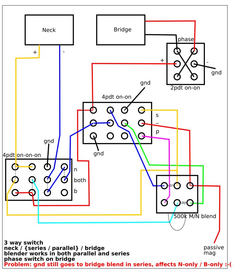
Perhaps that's just asking too much.
P.S. sorry for bumping this old thread, but it seemed like a good place to add this idea.
I was quite happy with the following configuration, until I noticed that single-pickup selection won't work well when in series mode, because the bottom side of the blender will still have a ground attached to the green wire.
Basically, I would need two more columns in the on-on-on switch to do the same thing I do with the neck -, but I don't think a switch like that exists...
Perhaps that's just asking too much.
P.S. sorry for bumping this old thread, but it seemed like a good place to add this idea.
One idea could be modding the 4pdt to make the two right-hand side column to only be closed when the switch is in the middle position, then I would have enough contacts to make things work.
I'm not sure how easy that is to do, but I'll think about it. If anyone has any experience with that, tips would be highly appreciated!
I'm not sure how easy that is to do, but I'll think about it. If anyone has any experience with that, tips would be highly appreciated!
This should work using a 3PDT switch. Separate tone controls can be used, if desired.
Full schematic in parallel:
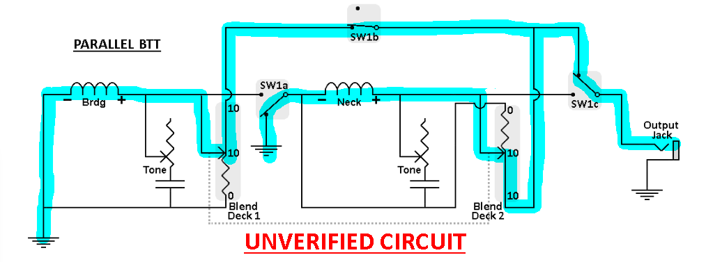
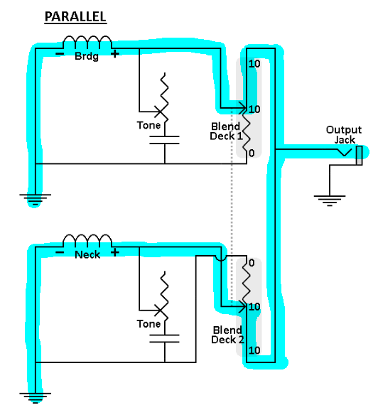
It's the same as the basic, everyday parallel blend circuit we've all grown to know and love.:
Here's the full blend circuit switched to series:
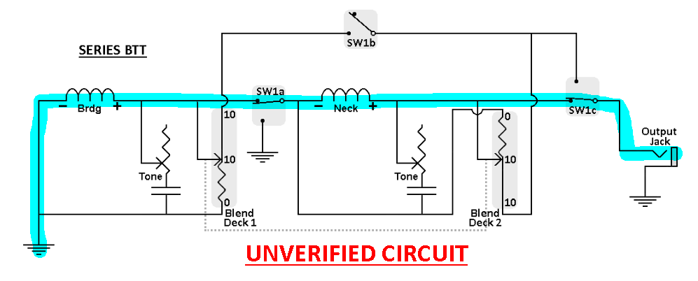
The same as only a series blend:
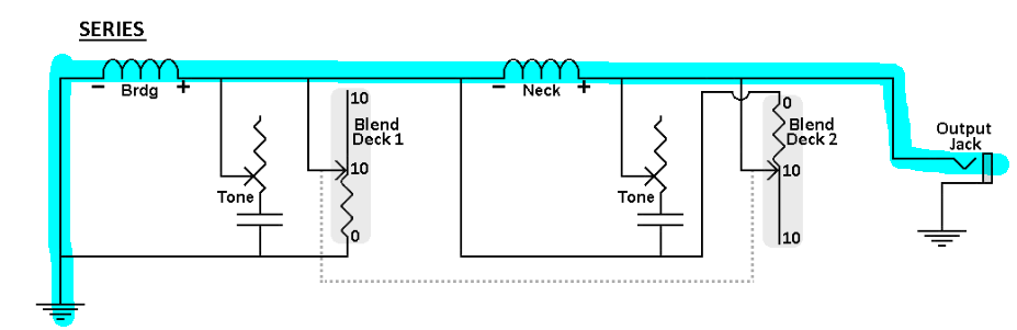
Separate volume pots can be used also (my preference).
As discussed in the forum, for parallel mode only, isolation resistors (a great idea, in my opinion) can be used to keep tone controls isolated from each other when both volumes (blend control centered) are at 10. Doesn't interfere with series mode.
I stamped "UNVERIFIED" because I haven't built it to test it yet. Don't think anyone else has either.
Anyway, thought I'd throw this out.
Full schematic in parallel:
It's the same as the basic, everyday parallel blend circuit we've all grown to know and love.:
Here's the full blend circuit switched to series:
The same as only a series blend:
Separate volume pots can be used also (my preference).
As discussed in the forum, for parallel mode only, isolation resistors (a great idea, in my opinion) can be used to keep tone controls isolated from each other when both volumes (blend control centered) are at 10. Doesn't interfere with series mode.
I stamped "UNVERIFIED" because I haven't built it to test it yet. Don't think anyone else has either.
Anyway, thought I'd throw this out.
Thanks for your input fig!
I agree: if you don't want the additional three-way switch to quickly go to neck-only or bridge-only and bypass the blender completely, the circuit can be done with a blender + 3pdt.
Actually, I think you still need a 4pdt if you want the blender to be ungrounded in parallel mode, which is what I am looking for.
In my case, however, I would also like to have the 3-way switch to select:
Position 1: neck only (bypass blend)
Position 2: neck + bridge, in parallel or series depending on switch, with blend working in both modes
Position 3: bridge only (bypass blend)
I think the circuit I sent above does work, except for the issue I mentioned: when in series mode (4pdt up) there remains a ground connection to one of the two blend decks (green wire in my figure). The issue with that is that, when selecting positions 1 or 3 with the three-way switch, the blender will be in the way and, will work like a volume.
What I have in mind is modding the 4pdt on-on-on used as 3-way switch (bottom left in my figure) so that the rightmost two colums will only connect the two outer pins when the switch is in center mode. That way, I can use those two columns to disconnect the grounds from the blender in positions 1 and three.
Without the mod, I can only disconnect one of the two, because I need two columns for that (see what happens to the neck - in my circuit diagram).
I ordered a couple on - off - on full-sized toggle switches, I think the mod should be possible on those by bending the internal connectors and adding a couple small springs (still have to find the right ones)..
If anyone can think of a different solution, I'd be more than happy to skip the switch modding fun :-D
I agree: if you don't want the additional three-way switch to quickly go to neck-only or bridge-only and bypass the blender completely, the circuit can be done with a blender + 3pdt.
Actually, I think you still need a 4pdt if you want the blender to be ungrounded in parallel mode, which is what I am looking for.
In my case, however, I would also like to have the 3-way switch to select:
Position 1: neck only (bypass blend)
Position 2: neck + bridge, in parallel or series depending on switch, with blend working in both modes
Position 3: bridge only (bypass blend)
I think the circuit I sent above does work, except for the issue I mentioned: when in series mode (4pdt up) there remains a ground connection to one of the two blend decks (green wire in my figure). The issue with that is that, when selecting positions 1 or 3 with the three-way switch, the blender will be in the way and, will work like a volume.
What I have in mind is modding the 4pdt on-on-on used as 3-way switch (bottom left in my figure) so that the rightmost two colums will only connect the two outer pins when the switch is in center mode. That way, I can use those two columns to disconnect the grounds from the blender in positions 1 and three.
Without the mod, I can only disconnect one of the two, because I need two columns for that (see what happens to the neck - in my circuit diagram).
I ordered a couple on - off - on full-sized toggle switches, I think the mod should be possible on those by bending the internal connectors and adding a couple small springs (still have to find the right ones)..
If anyone can think of a different solution, I'd be more than happy to skip the switch modding fun :-D
Yeah, I took a look at the ungrounded blend thing when I was drawing this up. I couldn't get it out of the 3pdt switch. Needs more contacts, like you said....if you want the blender to be ungrounded in parallel mode...
Hey I know this is like multiple years later but it seems this thread has been active on and off for about three so I figured what’s one more? If you’re still active, I wanted to point out that at full on or full off that series resistance doesn’t actually make a difference (at full on the series resistance is 0, and at full off the pickup gets shorted out anyway), but I agree there is a pretty obvious difference in all of the in-between area. What I wanted to ask you is 1) how do you think this would affect tone (it obviously will but I honestly have no clue what the result would actually look like) and 2) do you think it maybe affects taper also, and if so, in what ways? Also, I wanted to thank you for poking holes in this even a year after the matter, I wasn’t very experienced then and still ain’t for the most partAlthough both the 3PDT and the 4PDT schemes should work, the way the blending is done is different:
In both cases the M/N pot redirects the current around one of the pickups to provide the required continuity but in the 3PDT scheme, the blend pot additionally introduces series resistance to the pickup, similar to a regular, grounded volume pot.
It seems to me that this would introduce addtional, unwanted changes to the signal. What do the experts say?
Last edited:


