• TalkBass has been independent since 1998. Add your voice.
    Create a free account to reply to discussions, view embedded media, and browse with fewer display ads.
    Join freeLog in
    Want zero display ads or expanded classifieds tools? Compare plans.

1969 Ampeg SVT Restoration Thread

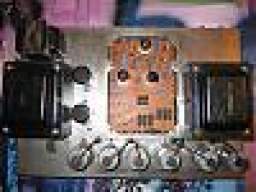
Here's just a couple of picks as the amp looks now. I am sitting down to disassemble and start cleaning it now.

svt1.JPG svt2.JPG

I'll update this thread with pictures as progress is made.

Here's a link to my initial NAD thread:

Just got a '69 SVT for 0 | TalkBass.com
 
Looks like they missed that electrolytic cap in the preamp nvm looks like the new one is just to the side of the old one. It's definitely seen some stuff, but everything is fixable. Especially when you pick it up on the cheap.
 
Last edited:
  • Like
Reactions: Funk With Me
  • Like
Reactions: beans-on-toast
Here are quite a few shots of the main PCB. I concentrated the images on areas where hook-up wires are soldered. Some burnt components for sure. Quite a few mods. Some traces cut, some added or repaired. Some resistors put on the back side of the board. Some cold solders. Some broken solder. One of the stand-offs is broken. Who knows how far various component values have drifted...

It is difficult to work on this board while it's in the chassis. I'm considering removing it, cleaning it thoroughly, repairing the traces and completely repopulating it with new, high quality parts. Thoughts?

Regarding the output transformer: it is obviously (relatively) new. Shiny and clean. One photo below shows the only markings beside the "Made in Japan" sticker. What's going on here? Is this an MTI-era NOS transformer? Should I be concerned about the quality of this OT?

IMG_0287.JPG IMG_0290.JPG IMG_0291.JPG IMG_0292.JPG IMG_0293.JPG IMG_0294.JPG IMG_0295.JPG IMG_0296.JPG IMG_0297.JPG IMG_0298.JPG IMG_0299.JPG IMG_0302.JPG
 
Sometimes people remove the PCB to clean and restore it. Makes working on it easier. Some parts will be within spec, others may not be. Changing them all adds to the cost but it is you choice. The plate and screen resistors act as fuses, do not replace them with with higher wattage components, stick with what is specified on the schematic. Buy extra and match them. It is also important to match the one ohm cathode resistors.

Cement block wire wound resistors are good to use. When they fail, they tend to blow from the bottom. If you look at one, the bottom looks different than the other sides, you can see that it is filled with glue. When you mount these resistors, leave a mm or so between the resistor and the PCB. Also, rotate them so the bottom of the resistor is facing to the side so that if it does blow, the flames don't go towards the board and damage it.

Other than the plate and screen resistors, if you replace any 1/2w resistors, I use 2w metal film, Yageo FMP200 series. Digi-Key is one place that sells them.

As was mentioned, that big brown cap in the preamp near the switches is original, it should probably be changed.

I wouldn't be concerned about the output transformer. I've never heard any complaints about the ones that MTI used. If you are concerned, fliptops sells a nice replacement made by Heyboer in the US.

There was a factory mod that cut some traces on the PCB. This is detailed on the early schematics that I think that I recall passing on to you. Let me know...
 
Last edited:
There are a lot of things barnacled on there but nothing insurmountable. I think I'd also recommend pulling the PCB out as it makes it a lot easier to work on. What's the grey/silver crap on the corner of the power amp PCB? Or maybe "What was it" is a better question as it seems to be gone in some of the other pics.
Nice score for $500 for sure!

That was silicone gasket material. I have no idea why it was there. And, yes, I cleaned it off.
 
That was silicone gasket material. I have no idea why it was there. And, yes, I cleaned it off.

Weird. At least you could get it off. :D

I would definitely check all of the carbon comp resistors for drift and replace any that are out of spec or you can just replace all of them. That's not a very expensive proposition. There was a lot of crusted on flux left on the PCBs in mine so I went at it with a can of flux remover and cleaned it all up. Boards looked much better now.

And since we're on the topic of SVT restoration/preservation, the outsides of my transformers are beginning to rust a bit. Is there something I can coat them with to stop that? Shellac of some kind or something?
 
And since we're on the topic of SVT restoration/preservation, the outsides of my transformers are beginning to rust a bit. Is there something I can coat them with to stop that? Shellac of some kind or something?

A little rust is not a bad thing, it acts as an insulator. Too much that gets under the plates can be an issue. But I don't like the rust being there.

This is what I do:
  • Gently brush off any loose rust. Do not use a wire brush that can scratch the plates.
  • Prep the edges of the plates with an acetone rinse. I wipe it down with a cotton makeup removing pad.
  • I stabilize the rust that remains and seal it by dabbing on a coat of MG Chemicals 4228 (Red GLPT Insulating Varnish | MG Chemicals. It makes it look like new. You don't use very much to do both transformer so a small bottle will do. They also sell a product called Super Corona Dope (Super Corona Dope | MG Chemicals) that I've used. It dries clear, the other product leaves a red/orange tinge that is close to what was used originally.

I was told by Mercury Magnets that an oil based urethane will seal it. Also a rust paint would work.
 
Last edited:
A little rust is not a bad thing, it acts as an insulator. Too much that gets under the plates can be an issue. But I don't like the rust being there.

This is what I do:
  • Gently brush off any loose rust. Do not use a wire brush that can scratch the plates.
  • Prep the edges of the plates with an acetone rinse. I wipe it down with a cotton makeup removing pad.
  • I stabilize the rust that remains and seal it by dabbing on a coat of MG Chemicals 4228 (Red GLPT Insulating Varnish | MG Chemicals It makes it look like new. You don't use very much to do both transformer so a small bottle will do. They also sell a product called Super Corona Dope (Super Corona Dope | MG Chemicals that I've used. It dries clear, the other product leaves a red/orange tinge that is close to what was used originally.

I was told by Mercury Magnets that an oil based urethane will seal it. Also a rust paint would work.

Awesome! I figured you would have the solution. :D I think we have Corona Dope downstairs at work so I might be able to snag some. Thanks!
 
  • Like
Reactions: beans-on-toast
Here's my old website for my 1970 that I had to refurbish. You can see what my PCB looked like and chassis. Invalid Link Removed
I removed the PCB and all parts and cleaned it up. Replaced every part with a new one.
The conversion to 6550's would have added some of the trace cuts, my PCB has the cuts and mods done that were somewhere between 69-70.
One thing I know about my 70 with 6146's vs every 6550 SVT I have tested is that bench testing into a 4 ohm load checking max power before clipping, my 6146 does about 360-370 clean!!! Every 6550 one I have tested which is several have done maybe 270 max... This is with GE's or any other 6550/KT88 type tube....
Those switches are the correct ones for an early aluminum chassis SVT...
 
Here's my old website for my 1970 that I had to refurbish. You can see what my PCB looked like and chassis. Invalid Link Removed
I removed the PCB and all parts and cleaned it up. Replaced every part with a new one.
The conversion to 6550's would have added some of the trace cuts, my PCB has the cuts and mods done that were somewhere between 69-70.
One thing I know about my 70 with 6146's vs every 6550 SVT I have tested is that bench testing into a 4 ohm load checking max power before clipping, my 6146 does about 360-370 clean!!! Every 6550 one I have tested which is several have done maybe 270 max... This is with GE's or any other 6550/KT88 type tube....
Those switches are the correct ones for an early aluminum chassis SVT...


You did a good job at cleaning it up, it shows how well these old amps can be restored. Yours certainly had a lot of rust. My '71 6550 based SVT was a basket case but not as bad as that!
 
I haven't done a whole lot on the amp since my last post. I'm not going to pull the pcb etc. until I have stared at it a few more hours.

I've started collecting tools. Even though I already have several garden-variety irons, I'm going to buy a good soldering iron this week.

I was having trouble with an exhaust fan motor thermalling off last week (day job stuff). I had to borrow a meter with a current clamp to see how many amps it was pulling. Anyway, I lamented my cheapo meter to my friend that happened to be at the bar where the exhaust fan was and he GAVE me a NIB Fluke 179. The exact model that beans-on-toast had recommended to me. So there's that.

I'm currently engaged in getting a plan together. Sort of a play book. The gray painted strip at the top of the face plate has a good chunk of paint missing. It has been suggested (again by beans-on-toast whose input I value greatly) that it could be powder coated. I have a powder coating place I use and they do great work but I know the process subjects the piece to some amount of heat. Enough to melt plastic for sure. Is there any concern the blue graphics could be damaged?
 
Last edited:
Really exciting news revealed by @Bill Hughes in another thread: they made only 50 of these amps. I'm assuming most of those went to touring artists. I'm working on finding out as much as I can about mine. Of course, it being a prototype, it has no serial number. So far the person I got it from has not provided any info.

I've decided to do a total tear down and restoration.

After spending a few minutes here and there alternately looking at the schematic and peering into the chassis with its ganglion cyst of wires, I decided to start disassembling the amp staring with the power amp PCB.

I drew a map of the board indicating where each of the 45 wires attach; numbered and labeled each wire and their respective spot on the board. I consulted the schematic as I went in an effort to make some sense of it all. Removing tube and cap sockets now. Transformers, pots, jacks and switches etc. next.

IMG_0322.JPG IMG_0323.JPG IMG_0324.JPG IMG_0325.JPG
 

Attachments

  • IMG_0326.JPG
    IMG_0326.JPG
    453.8 KB · Views: 513
  • Like
Reactions: S-Bigbottom