
This might help sort out the wiring. It is from a later revision so there will be some differences.
HOLY MOLY!!! That's awesome, Beans! Thank you!
How would I go about printing a new board? This one is all hacked-up.

TalkBass has been independent since 1998. Add your voice.
Create a free account to reply to discussions, view embedded media, and browse with fewer display ads.
Join free Log in
Want zero display ads or expanded classifieds tools? Compare plans.
This might help sort out the wiring. It is from a later revision so there will be some differences.
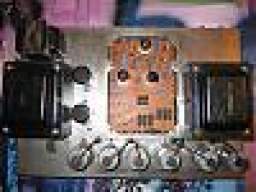

How would I go about printing a new board? This one is all hacked-up.
Yeah look like it has been repaired like the one trace burned up and lifted. Some of the other stuff is probably from being converted to 6550's. Too bad they installed that power cable plug, cut up the chassis on that rare one!
That came from the attached 77 service manual.
A new board would be great. I'm not aware of any replacement boards for the vintage SVT on the market. There is a reproduction one for the main board for the V4 family available on ebay: Ampeg V2 V4 VT22 V4B Main Printed Circuit Board Replacement | eBay.
I don't know if they would be willing to do a board for you. A new board would have to be designed and it would be costly to produce in single numbers. On the plus side, it's a relatively simple, single sided board. A thicker FR4 board would be nice, as would plated through holes, perhaps double up some of the traces, top and bottom layers, that tend to get damaged when plate and screen resistors blow.
It helps when installing these resistors to offset them from the board by a mm or so. If cement block resistors are used, turn them so that the bottom where the glue is, is not facing the board. Flames often erupt from the bottom when they blow. Pointing them away from the circuit board and offsetting their mount helps reduce the chances of damage. When replacing these parts, don't exceed the wattage specified on the schematic. They blow like a fuse when there is a problem. This is a good thing as it can protect the output tubes and transformer. Upping the wattage will prevent the resistors from blowing. I like to buy extra and match the plate, screen, and cathode resistors when replacing them.
How to deal with damaged traces. If they are lifted, they can be glued down. I use a high temperature marine epoxy from J-B Weld. Some people use cyanoacrylate (crazy glue). Never tried it to repair boards. If traces or pads are missing, bus wire can be soldered onto a good trace and run to where you need it. Not pretty, but it works.
Be careful when soldering. Too much heat can lift the traces. So can strong solvents that are used for cleaning.

If traces or pads are missing, bus wire can be soldered onto a good trace and run to where you need it. Not pretty, but it works.
What about that metal paint used to repair traces?
I repaired an amp once that a previous "tech" used solder wick to repair a blown out trace!I've seen them used on fabric with wearable electronics. Never tried the paint on trace repair products. You need to have enough copper to handle the current.
If the trace is wide enough, you can precut a patch from a sheet of copper and glue that to the board. There are alternatives, sometimes you need to get inventive.
I repaired an amp once that a previous "tech" used solder wick to repair a blown out trace!


Gonna get nice ceramic tube sockets for this baby.
Be careful, not all the current ceramics are good. The metal terminals don't pinch the tube pins well. There are some nice teflon ones at partsconnexion and original replacements are available if you are interested. When you reinstall the sockets, I like to twist the power tube heater wires to minimize the noise. They typically aren't on these amps. Follow these guidelines at the bottom of the page: The Valve Wizard
Yes you can remove the end caps on the transformers. Be very careful. There are insulating washers on some transformers that need to be there. Paint works but if you can find a local powder coater, the finish is superior.


Yes. The plates are usually stuck together well. Just treat it with kid gloves. Note how tight the bolts are, you want them retightened evenly and with about the same tightness. As I said, you don't want the bolts shorting the plates.
Some modern sockets do not make a tight contact with the tube pins. New sockets need to be retensioned. Jule had some interesting comments in this thread: #252. A socket with a clamshell contact is good. I like these [Invalid or Expired Link Removed] You would have to ask them about mounting rings and their dimensions. Since you have holes in the chassis, you want to reuse them. That can be a problem. Using the same socket would make that easier: NOS- A8F4 - 8 Pin - Sockets, Adapters and Parts
How are you planning to clean the chassis? Are going to leave it bare metal? Being on the water, do things tend to rust easily where you live?
Yes, we are in a highly corrosive enviroment. Im not sure about cleaning the chassis. I was thinking of having the chassis powder coated. There may even be clear powder coating.
No question that they can do some amazing stuff with powder or ceramic. I stopped painting as a result.
I've also had some SVT grey front panels powder coated. So if you get the chassis done, that panel can be done as well.


