
• TalkBass has been independent since 1998. Add your voice.
    Create a free account to reply to discussions, view embedded media, and browse with fewer display ads.
    Join freeLog in
    Want zero display ads or expanded classifieds tools? Compare plans.

Active preamp, no EQ

I can't remember what they are called right not but they do make little pcb's that "convert" smt to thru-hole.

Oddly enough, they are called 'SMD or SMT adaptors'. SMD/T being 'surface mount device/technology' obviously. It took me an embarrassingly long 10 minutes on google to figure this out.

"Better" in what regard? You can study specs all day, but better specs do not necessarily mean it will sound better.

Mostly the indication in the specsheets that the OPA134 and 1641 are optimized for audio applications. The TLE2071 isn't necessarily 'tuned' for audio applications. The primary written differences are unity gain stability and better performance with a single sided power supply. The TLE2071 requires the input to be DC biased to 1/2 of the supply voltage and no indication of unity gain stability. There may be other things the designers do (like minimize phase shifts across a wider spectrum) that aren't written down.

Fortunately, the PCB from GGG already has the input DC biasing built in.
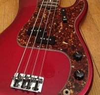
 
Is there a way I could get an active preamp without an onboard EQ? I like the low impedence, reduced signal loss and higher output that can be provided by having an active preamp, but I don't want to mess around with an onboard EQ.

What do you guys recommend?
engineers :rolleyes:

skipping over the 6 pages of jfet and opamp discussions for an OP who says he doesn't even know how to use a soldering iron, an EMG PA-2 will make a perfectly good buffer. stuff it inside the control cavity with the boost switch set to "off" and you have unity gain, or switch it to "on" and tweak the level trimpot up just a pinch and you'll have a clean volume increase. (the distortion comes when you dime that level trimpot and blast the front end of your amp.)

run your regular volume and that rotary switch first.
 
hey kingrazor,
have you decided what you are going to do?

walterw has a point. his suggestion should work but it's almost $50.
if you are willing to put in some time or patience and possibly learn a few new tricks you could save some $$$,

There aren't too many DIY projects that you could actually save money - onboard electronics are an exception.
 
hey kingrazor,
have you decided what you are going to do?

walterw has a point. his suggestion should work but it's almost $50.
if you are willing to put in some time or patience and possibly learn a few new tricks you could save some $$$,

There aren't too many DIY projects that you could actually save money - onboard electronics are an exception.
Well, it's hard to say.

I have one bass guitar right now. I have a second one coming in a few months. After I get the new bass, I plan on giving away my first one to a friend. Which makes me think maybe I shouldn't mess with the electronics on it.

The new bass has some fancy EQ stuff on it that I may want to gut and replace with a buffer for simplicity. I'm just not sure yet, for now I think I'll wait on this.

Thanks for the helpful info though, I'm sure I'll want to do something like this in the future.
 
Well, it's hard to say.

I have one bass guitar right now. I have a second one coming in a few months. After I get the new bass, I plan on giving away my first one to a friend. Which makes me think maybe I shouldn't mess with the electronics on it.

The new bass has some fancy EQ stuff on it that I may want to gut and replace with a buffer for simplicity. I'm just not sure yet, for now I think I'll wait on this.

Thanks for the helpful info though, I'm sure I'll want to do something like this in the future.

I agree, makes sense to wait.
Regardless of what you decide to do, if you need help let me know if you need help.

Who knows - I may have designed and tested a buffer at that time. That's the direction I was looking at for some time.
 
Already offered via PM. He has different plans for the bass we've been discussing and doesn't need it. I'll offer it here on TB once I have the replacement ready.
Once you're sure the replacement works and you're sure you don't need it. Go ahead and offer it on TB. It would probably be nice to have one just in case but like I said I wouldn't have a use for it for a few months at least.
 
Got the op amp buffer installed - everything works.

Here's what I gained - much lower noise levels when connected to 9v power supply. Not zero but much better than with the JFET. I put the buffer LED through the front of my guitar so it turns on when the guitar is active and shows which side of the DPDT switch is the 'active' side.

Here's what I lost - the 3-6dB of gain I got with the JFET buffer. Not a big deal and could be compensated for at the external preamp.

Notes - I just used the parts per the GGG design - no extra caps, no additional gain resistors. Everything seems reasonably stable and my tone is no longer affected by the cable length (within reasonable limits). I skipped the gain resistors because I realized I'd have to redo the input DC bias resistors too and I didn't want to wait until tomorrow when radioshack opens to finish this up.

The GGG circuit board is much neater than my prototype.
 
Got the op amp buffer installed - everything works.

Here's what I gained - much lower noise levels when connected to 9v power supply. Not zero but much better than with the JFET. I put the buffer LED through the front of my guitar so it turns on when the guitar is active and shows which side of the DPDT switch is the 'active' side.

Here's what I lost - the 3-6dB of gain I got with the JFET buffer. Not a big deal and could be compensated for at the external preamp.

Notes - I just used the parts per the GGG design - no extra caps, no additional gain resistors. Everything seems reasonably stable and my tone is no longer affected by the cable length (within reasonable limits). I skipped the gain resistors because I realized I'd have to redo the input DC bias resistors too and I didn't want to wait until tomorrow when radioshack opens to finish this up.

The GGG circuit board is much neater than my prototype.

did you get the discrete jfet board?
 
did you get the discrete jfet board?

No, does GGG have one? I got the op amp board. Total cost for the whole buffer, including electronic parts and shipping was under $20 although I have the benefit of having already pre-wired my passive guitar to accept the buffer. The JFET buffer has so few parts I think the only thing that suffers from not having a printed board is appearance.

Speaking of appearance, I used hot glue as my conformal coating/potting compound. Looks like heck and I'm sure the pioneers of electronics are highly offended but works really well to avoid shorts.

The guitar is red so the red LED indicator light actually looks kinda cool when it's on.

I found out I can't post in the classifieds unless I make a contribution to TB. Seems I have to contribute money here to give away something for free.
 
No, does GGG have one? I got the op amp board. Total cost for the whole buffer, including electronic parts and shipping was under $20 although I have the benefit of having already pre-wired my passive guitar to accept the buffer. The JFET buffer has so few parts I think the only thing that suffers from not having a printed board is appearance.

Speaking of appearance, I used hot glue as my conformal coating/potting compound. Looks like heck and I'm sure the pioneers of electronics are highly offended but works really well to avoid shorts.

The guitar is red so the red LED indicator light actually looks kinda cool when it's on.

I found out I can't post in the classifieds unless I make a contribution to TB. Seems I have to contribute money here to give away something for free.

The only reason I ask if you went with the discrete jfet kit (strato-blaster) is that you said you had a 3 db loss.
Does your proto-type have gain?

Also, if I remember correctly, you mentioned that with your proto-type your power supply decoupling was at the jack (?). Try moving to the pcb. It is important to have power supply decoupling as close to the device as possible.
 
The only reason I ask if you went with the discrete jfet kit (strato-blaster) is that you said you had a 3 db loss.
Does your proto-type have gain?

Also, if I remember correctly, you mentioned that with your proto-type your power supply decoupling was at the jack (?). Try moving to the pcb. It is important to have power supply decoupling as close to the device as possible.

Yes, the JFET buffer has 3-6dB of gain by my highly calibrated ears. This is largely the result of having to optimize current draw on the JFET to increase battery life driving the selection of the resistors to set the bias current low and ensure adequate headroom below the upper rail to avoid clipping. Gain was an outcome, not an input. Going to a unity gain opamp obviously did away with the boost but the guitar still sounds great.

I'd say the opamp version cleaned up the treble a little bit over the JFET. I'm not sure if it's because of the peculiarities of the JFET (it's not a true linear device) or because the rest of the design has less impact on the tone (change in pup loading due to change in input impedance?) or my overactive imagination.

By the way, thanks for all the tips and dialog on this - it kept me motivated and informed.
 
Yes, the JFET buffer has 3-6dB of gain by my highly calibrated ears. This is largely the result of having to optimize current draw on the JFET to increase battery life driving the selection of the resistors to set the bias current low and ensure adequate headroom below the upper rail to avoid clipping. Gain was an outcome, not an input. Going to a unity gain opamp obviously did away with the boost but the guitar still sounds great.

I'd say the opamp version cleaned up the treble a little bit over the JFET. I'm not sure if it's because of the peculiarities of the JFET (it's not a true linear device) or because the rest of the design has less impact on the tone (change in pup loading due to change in input impedance?) or my overactive imagination.

By the way, thanks for all the tips and dialog on this - it kept me motivated and informed.

a jfet input op amp and a discrete jfet should have similar input impedances...depending on the device of course.

again, without having your prototype in my hands, I still suspect power supply decoupling.

since you can't give away the op amp kit away and kingrazor doesn't want it - keep it. that should be enough reason to get another bass. :D
 
a jfet input op amp and a discrete jfet should have similar input impedances...depending on the device of course.

again, without having your prototype in my hands, I still suspect power supply decoupling.

since you can't give away the op amp kit away and kingrazor doesn't want it - keep it. that should be enough reason to get another bass. :D

LOL, I'm working on it. I found a nice BTB405 I'm Jonesing for.

The input impedance difference is in the circuit, not the device. The JFET circuit has a 3M input while the opamp version has 1.1M input.

I found a better buffer kit here:
http://www.buildyourownclone.com/confidence.html
I'm going to make my own looper and add one of these buffers to it or swap in my unity gain opamp buffer and put this one in my frankenbass. It has dialable gain and runs about $22 shipped.
 
LOL, I'm working on it. I found a nice BTB405 I'm Jonesing for.

The input impedance difference is in the circuit, not the device. The JFET circuit has a 3M input while the opamp version has 1.1M input.

I found a better buffer kit here:
http://www.buildyourownclone.com/confidence.html
I'm going to make my own looper and add one of these buffers to it or swap in my unity gain opamp buffer and put this one in my frankenbass. It has dialable gain and runs about $22 shipped.

I'ld be interested to hear your opinion of that ckt.

I looked at the schematic and say a couple thinkg I'm not too sure about. The final BJT stage isn't really necessary. If that is where gain is achieved it would be better to do in at the op amp. Since the signal is taken off the collector the output impedance would would be lower at the op amp.
 
I'ld be interested to hear your opinion of that ckt.

I looked at the schematic and say a couple thinkg I'm not too sure about. The final BJT stage isn't really necessary. If that is where gain is achieved it would be better to do in at the op amp. Since the signal is taken off the collector the output impedance would would be lower at the op amp.

The main reason BJTs are added to the output in opamp buffer circuits is to provide a power stage. I'm not sure as to whether or not it's necessary as I haven't experimented with a lot of these. I've seen similar designs with a BJT power stage after a JFET buffer stage. IIRC, BJTs are used there because they color the signal less than JFETs (more linear). In the big scheme of things, this is a relatively low stress application for these kinds of circuits and I'm not too picky about tone as long as the signal is clean. You're right though, the gain pot would be better in the buffer stage.

I like it in a looper since it's not clear that all the boxes I might want to use have high input impedance. I bought parts for a 5 switch looper from pedalpartsplus - $85 shipped including powercoat and will add this buffer to that.
 
The main reason BJTs are added to the output in opamp buffer circuits is to provide a power stage. I'm not sure as to whether or not it's necessary as I haven't experimented with a lot of these. I've seen similar designs with a BJT power stage after a JFET buffer stage. IIRC, BJTs are used there because they color the signal less than JFETs (more linear). In the big scheme of things, this is a relatively low stress application for these kinds of circuits and I'm not too picky about tone as long as the signal is clean. You're right though, the gain pot would be better in the buffer stage.

I like it in a looper since it's not clear that all the boxes I might want to use have high input impedance. I bought parts for a 5 switch looper from pedalpartsplus - $85 shipped including powercoat and will add this buffer to that.

yes, but mostly no.
That BJT stage is typically an emitter follower stage and is meant as a power stage - current is amplified, not voltage. These stages are used in power amplifier topologies, large power amplifiers and op amps, but are one part of a circuit. This stage needs to be included within a feedback loop to overcome the 0.6V (Vbe) drop that is inherent in an emitter-follower.
The emitter-follower has very low output impedance and is important in this application.
The op amp is more than capable to drive the signal. The input of the next stage is typically a high input impedance, so we are dealing with signal (voltage), not power or current drive.
The output stage of any JFET op amp is a BJT. On JFET op amps the only JFET is the input stage.

The output in this ckt is taken off of the collector which has a higher output impedance that if taken of the emitter. This impacts 2 things - frequency response and creates a high impedance path. High impedance paths pick up noise.