• TalkBass has been independent since 1998. Add your voice.
    Create a free account to reply to discussions, view embedded media, and browse with fewer display ads.
    Join freeLog in
    Want zero display ads or expanded classifieds tools? Compare plans.

Ampeg PF-50T Humbuster

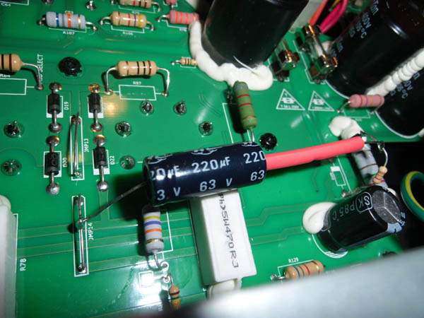
May I suggest that the position of the 220uF capacitor be adjusted so that it isn’t as close to the cement block power resistor. It could be the image angle but it looks as if they are in contact.

A local hot spot on an electrolytic cap is best avoided.


DA6F7A0C-E34C-48E2-AFA4-870E177EA0B7.jpeg
 
Last edited:
Correct, it´s not the best location.
A 100V cap would be better than a 63V since it runs at about 60V. Mnats correctly put a 100V rating in his schemo of the mod. I would not have thought of it without his tracing in any case.

That cap was all I had at hand and I wanted to try it asap... (And still, it is swiss-clockwork standards compared to some of my homebrew tube amps...).
 
I think Bertr's fix (now on my Invalid Link Removed) is the best solution as it uses the existing externally accessible trim pot and will still give the 20 dB reduction in noise according to simulation. I'm going to convert mine back to original so I can add that to the video on my page, then use Bertr's mod to do some measurements. There are a million ways to do a negative bias circuit; I don't think we need to know more ways to implement it for the purpose of fixing the hum in this model.

About the hum, if you can't hear it and missed the warnings about cracking open your amplifier then you have two good reasons not to do it.

Regarding the board revision number they are different on the solder and component sides for reasons unknown. I will get around to posting images but for now I think the best way to identify the problem is to listen to your PF-50T with the gain and volume all the way down. If you are going to open the amplifier to check PCB revision numbers you may just want to see if the small number of bias components that match my schematic are present. Component designations on my circuit are correct and correlate to my PCB.

I also would like to point out that my amplifier as received matched the current Owner's Manual specification of a signal to noise ratio of 60 dB from 20 to 20kHz. Funny that @agedhorse was recently asking what specifications users wanted to see yet somehow this marginal specification gets overlooked...

The Subway specs include S/N ratio, as do some others.
 
Just picked up a PF-50T and did Bertr's extremely simple, inexpensive mod. The amp as purchased sounded great, but was clearly not suitable for studio use with that awful hum. I'm playing it through a PF-112HLF and miking the cabinet.

After the mod, it's maybe the best amp Ampeg has ever made, in my opinion. Certainly for studio use, with that inductor-based eq section. I had a B15-N back in the sixties. Owned a couple, and played through many SVT's over the years by way of comparison. The PF-50T/PF-112HLF reminds me a bit of all of my previous Ampegs, but more useful, and a lot easier to move around.

Many thanks to Mnats and Bertr for figuring this out and sharing! I would have never bought this amp if I hadn't read about this mod, as I was put off by the hum when I demoed it in the store.

It's still too early to tell, but it may be time to consider selling my REDDI. I would have never considered that before doing the mod on this amp.

Sad that Ampeg won't just rev the circuit board. Maybe they've got too many of the boards already fabricated? Anyway, the mod is highly recommended. Turns a good amp into a truly great one.

The sound and feel that comes out of this amp just isn't there with a class D power section in my experience. Tried all the popular brands (at all price ranges), though most of them use the same OEM power module supplier (Bang & Olufsen).

Plugging my G&L L-1505 into this rig makes the PF-50T/PF-112HLF growl like a wild animal.
 
Last edited:
The mod is not in the signal path so, no, it doesn't affect the tone. It just gets rid of the hum. Changing out your guitar cord would have much greater impact on the tone (seriously).

The amp is a fixed-bias, not auto-bias (cathode-biased) design, and the bias trimmer works just like it did before the mod. That's one of the nifty features of this particular implementation.
 
Last edited:
  • Like
Reactions: malpasso
The mod is not in the signal path so, no, it doesn't affect the tone. It just gets rid of the hum. Changing out your guitar cord would have much greater impact on the tone (seriously).

The amp is a fixed-bias, not auto-bias (cathode-biased) design, and the bias trimmer works just like it did before the mod. That's one of the nifty features of this particular implementation.
Thanx for being so clear for us, electronics dummies!!!
Then I think it is just a matter of time that I should tackle that mod!!!!
I do think that the pf-50t is the most marvellus piece of amp gear I have ever had!
:D
 
Stumbled across this gem today. Awesome. I use mine at home a lot and the hum is bothersome to me. I have been reducing it by setting the bias in a way that's off center according to the LED indicators. Cant recall if its cold or hot, but one or the other directions reduces the hum.

Now if I can only convince my EE son to do the mod for me sometime this century. :-)

I wonder what an official amp tech would charge. If I pay him that it might actually get done before he moves out of the house.
 
  • Like
Reactions: kobass
Stumbled across this gem today. Awesome. I use mine at home a lot and the hum is bothersome to me. I have been reducing it by setting the bias in a way that's off center according to the LED indicators. Cant recall if its cold or hot, but one or the other directions reduces the hum.

Now if I can only convince my EE son to do the mod for me sometime this century. :)

I wonder what an official amp tech would charge. If I pay him that it might actually get done before he moves out of the house.

The quote I got from a tech nearby me was $125. He stressed that he could not guarantee a satisfactory result. I'll be doing the mod myself when mine is out of warranty, and when I've finished my EE degree so I'll have a better understanding of what I'm looking at.
 
Last edited:
I will probably do the mnats mod which appears to be the easiest and least invasive surgery.

One question - I am in the USA and it appears that most of the mod posters here are from Europe. I realize the voltages after the power transformer should be the same, but am guessing that the frequency of the hum would be 60 hz in the USA vs the 50 hz in Europe.

Would you expect the results to be similar and would it be beneficial to change any of the capacitor or resistor values to mitigate the 60 hz USA hum?

Like one of the other posters, I have thought about getting rid of the amp and buying a REDDI but if it can be made silent that would change my tune.
 
At 60Hz the frequency of the bias ripple and therefore the resultant hum will increase in frequency but decrease in amplitude. It may explain why users in the US, Canada, Mexico et al. find the hum less objectionable. I don't think it explains why some say they do not hear it at all; we're bass players, right? We should be able to hear down to 50 or 60 Hz!

I recommend using Bertr's mod for the reasons outlined on my web page and mentioned in this thread though performance might be slightly better with my original fix. Not enough to worry about IMO. No value changes necessary.
 

Attachments

  • pf-50t_bias_original_60Hz.png
    pf-50t_bias_original_60Hz.png
    33.4 KB · Views: 147
  • pf-50t_bias_original_50Hz.png
    pf-50t_bias_original_50Hz.png
    33.6 KB · Views: 146
At 60Hz the frequency of the bias ripple and therefore the resultant hum will increase in frequency but decrease in amplitude. It may explain why users in the US, Canada, Mexico et al. find the hum less objectionable. I don't think it explains why some say they do not hear it at all; we're bass players, right? We should be able to hear down to 50 or 60 Hz!
I never hear it on a gig because there's plenty of competition with crowd noise, AC, and such drowning it out.
 
  • Like
Reactions: jdwinva and kobass
I never hear it on a gig because there's plenty of competition with crowd noise, AC, and such drowning it out.

True, but that doesn't help for studio use. Who here wouldn't pay an additional $50 for a 'hum free' model (the installation of less than $1 in parts at manufacturing quantity prices)? Kind of like the Fender Rumble 40: why not offer a model with a driver upgrade? I suppose those are decisions made by people who are experts on bass amps, like those in the marketing department... :-(
 
At 60Hz the frequency of the bias ripple and therefore the resultant hum will increase in frequency but decrease in amplitude. It may explain why users in the US, Canada, Mexico et al. find the hum less objectionable. I don't think it explains why some say they do not hear it at all; we're bass players, right? We should be able to hear down to 50 or 60 Hz!

I recommend using Bertr's mod for the reasons outlined on my web page and mentioned in this thread though performance might be slightly better with my original fix. Not enough to worry about IMO. No value changes necessary.

Thanks! One question about the bertr mod after studying the picture and struggling to follow the schematic (I'm a novice at this stuff) - I don't see the diode in the photo. I see the spot on the board where it was but don't see the diode itself. Maybe it's the lighting in the picture or maybe it's hidden behind the red heat shrink tubing? It looks like the added resistor is going straight to the board where one side of the diode was connected and it looks like the other end of that resistor goes straight to the big powder blue resistor and one side of the capacitor. I can tell from the description and the schematic that the diode is still in the circuit but can't see it and need to be able to clearly picture it in my mind before I attempt.

Thanks again!
 
True, but that doesn't help for studio use. Who here wouldn't pay an additional $50 for a 'hum free' model (the installation of less than $1 in parts at manufacturing quantity prices)? Kind of like the Fender Rumble 40: why not offer a model with a driver upgrade? I suppose those are decisions made by people who are experts on bass amps, like those in the marketing department... :-(

Reminds me of the Ashdown Retroglide amp that I had for a couple of days before returning it because the fan was REALLY loud and always on. The amp has since been discontinued but I would buy another one if not for the noisy fan.

Like the hum, that fan noise would be no big deal in a gig situation.
 
  • Like
Reactions: AstroSonic
Thanks! One question about the bertr mod after studying the picture and struggling to follow the schematic (I'm a novice at this stuff) - I don't see the diode in the photo. I see the spot on the board where it was but don't see the diode itself. Maybe it's the lighting in the picture or maybe it's hidden behind the red heat shrink tubing? It looks like the added resistor is going straight to the board where one side of the diode was connected and it looks like the other end of that resistor goes straight to the big powder blue resistor and one side of the capacitor. I can tell from the description and the schematic that the diode is still in the circuit but can't see it and need to be able to clearly picture it in my mind before I attempt.

Thanks again!

I think I see it now...

In the photo the new resistor is soldered to the board where one side of the diode was disconnected. Based on the schematic and logic, the other end of the resistor must be attached to the end of the diode that was disconnected from the board. It's hidden behind the red heat shrink so it's not visible in the photo but that must be where it is. Do I have that right? Can someone confirm?

Thanks.
 
I think I see it now...

In the photo the new resistor is soldered to the board where one side of the diode was disconnected. Based on the schematic and logic, the other end of the resistor must be attached to the end of the diode that was disconnected from the board. It's hidden behind the red heat shrink so it's not visible in the photo but that must be where it is. Do I have that right? Can someone confirm?

Thanks.

that sounds about right. you are cutting the leg where the diode (anode side of d29 if you speak schematic) connects to the board . one leg of the new 3.3k resistor is soldered to the board (where the diode used to be connected)while the other side of the 3.3k resistor is soldered to the diode. the capacitor has one leg soldered ground and the other leg is soldered between the new 3.3k resistor and the diode.
 
Very many thanks to Mnats and his research, a great read over at the Invalid Link Removed and to Bertr for figuring out the quick 2 component fix. (3.3kohm resistor and 220uf 100volt min electrolytic capacitor)

The hum on my amp was unacceptable for recording and has always bugged me at home and playing live. As a bass player I think am am very sensitive to 50Hz hum!! Now with the mod its is the best and quietest valve amp i have ever owned.

I just happened to have 450volt 220uf electrolytic capacitor (a bit over spec! I may replace with a radial cap at some stage) so I used it.

Here is my 'Bertr' mod:
I carefully desoldered the anode end of (1N4007) diode D29 using desolder wick to suck up the solder.
The new 3.3k resistor is soldered to the board where that side of the diode was desoldered from.
The negative of the new 220uf electrolytic capacitor goes to the floating union of the new 3.3k resistor and the now unsoldered anode end of the diode.
The positive of the capacitor to the link JMP14.
The whole mod floats nicely about 15mm above the board.

Also I echo Mnats words...dismantling - not to mention modifying - your amplifier will void the warranty. Tube amplifiers contain lethal voltages that remain even after being disconnected from power. Leave any work to an experienced electronics service technician.

Gaz
image1.jpeg
image2.jpeg
 
Last edited:
I think I see it now...

In the photo the new resistor is soldered to the board where one side of the diode was disconnected. Based on the schematic and logic, the other end of the resistor must be attached to the end of the diode that was disconnected from the board. It's hidden behind the red heat shrink so it's not visible in the photo but that must be where it is. Do I have that right? Can someone confirm?

Thanks.
Yes it is exactly that. In fact I did cut the leg of the diode leaving a bit sticking out of the board, to which I soldered the 3,3k (which at the other end is soldered to the bit of leg still part of the diode).
Doing a quicker mod would involve duct tape, and even I wouldn't dare...
 

Latest posts