
yep. it is 1/2 of its Vpp.
BTW, here's the 'corrected' pcb layout:
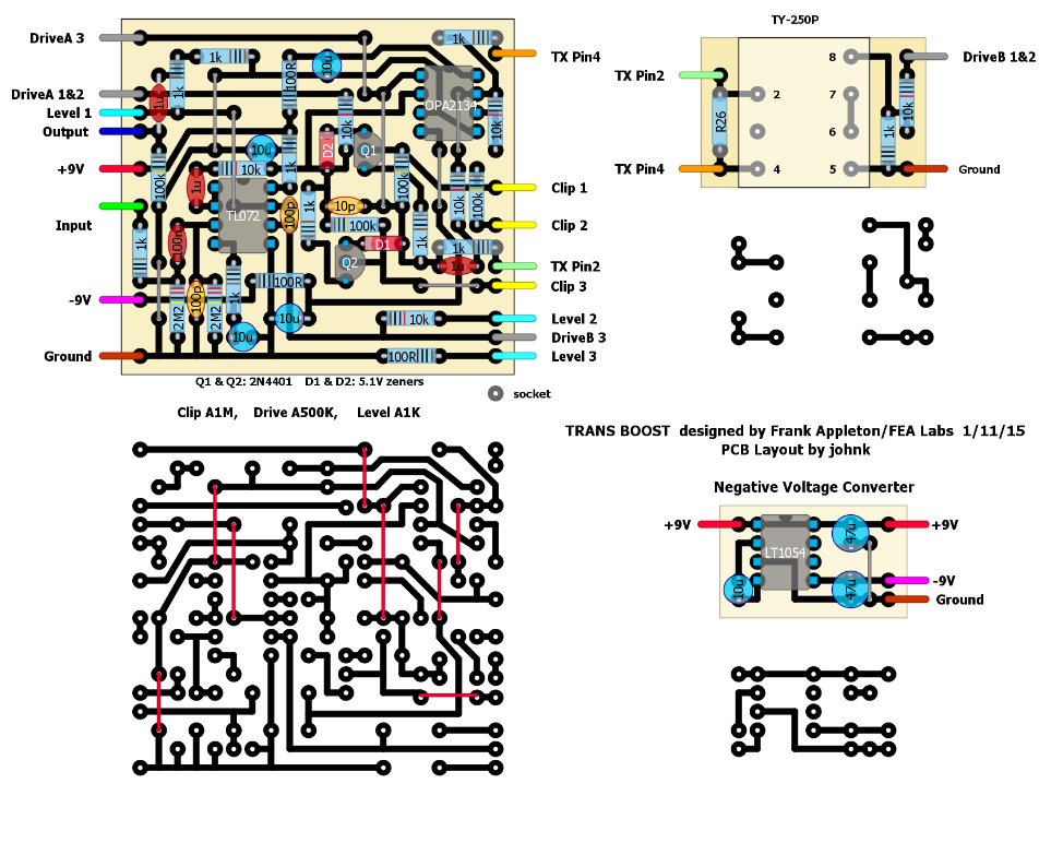
John, are Q1 and Q2 correct? It still looks like the emitters are connected to D1 and D2.
-Frank

TalkBass has been independent since 1998. Add your voice.
Create a free account to reply to discussions, view embedded media, and browse with fewer display ads.
Join free Log in
Want zero display ads or expanded classifieds tools? Compare plans.
yep. it is 1/2 of its Vpp.
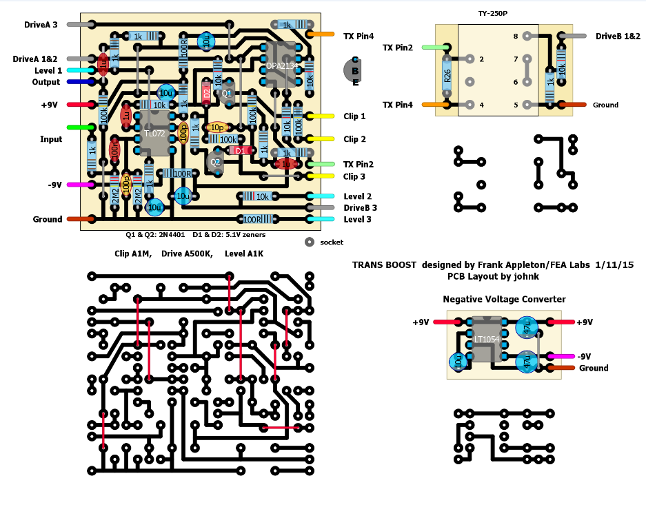
BTW, here's the 'corrected' pcb layout:

luckily they're socketed, so I just flipped them 180 degrees, but it still sounds exactly the same.John, are Q1 and Q2 correct? It still looks like the emitters are connected to D1 and D2.
-Frank
luckily they're socketed, so I just flipped them 180 degrees, but it still sounds exactly the same.
already tried that and there's no difference at all, with or without them.

got it. thanks. I'll have it all ironed out by tomorrow.
sorry for being an idiot.
 Thanx for hanging in there!
And thankx to both of you for discussing this so openly on a public forum. I find it very interesting to see how a new circuit is developed, tested and improved. (Even though most of the tech talk sounds like Chinese to me).
John, the load on U1b output may be too heavy for R4 and R5 to be 1K's. Please change R4 and R5 to 220R.
-Frank
The drive control is different... as it increases gain for U2a it simultaneously decreases gain for U1b (Please check with o-scope). I did it this way so that if you only want clean/non-clipped signals affected by the transformer characteristics, you do not have to worry about over-driving the output opamp.
The output opamp may still be loaded too much. Change VR2 to 5K and change R17 to 10K. This will give a lighter output load on U1b and allow for more gain/level control there.
-Frank
and yeah, there's no tranny installed yet for all of these tests with 2&8 jumpered.You should also have no tranny installed, no R26 installed and jumper 2-8 on tranny board.
-Frank

it gets louder if you turn the drive down right now. is that how it's supposed to be?


