I recently posted some pictures of an Aria Pro Magna Series II Bass that I have acquired in the Aria & Aria Pro II Club (Part Four) thread as I was curious to know which exact model it was. It was subsequently identified as being a MAB50.
The previous owner did say that he had had a problem with the electrics and that he had it repaired but didn’t tell me what the problem was.
However, I believe the that the blend control is not working as it should. Turning the control to one extreme has one pickup working only, middle has both pickups working and the other extreme also has both pickups working.
I posted this problem I was having in the other thread but thought I might be posting in the wrong place so I moved the continuation here.
Once again, and as stated in the other thread, I am a complete novice when it comes to guitars so apologies if I ask any stupid questions.
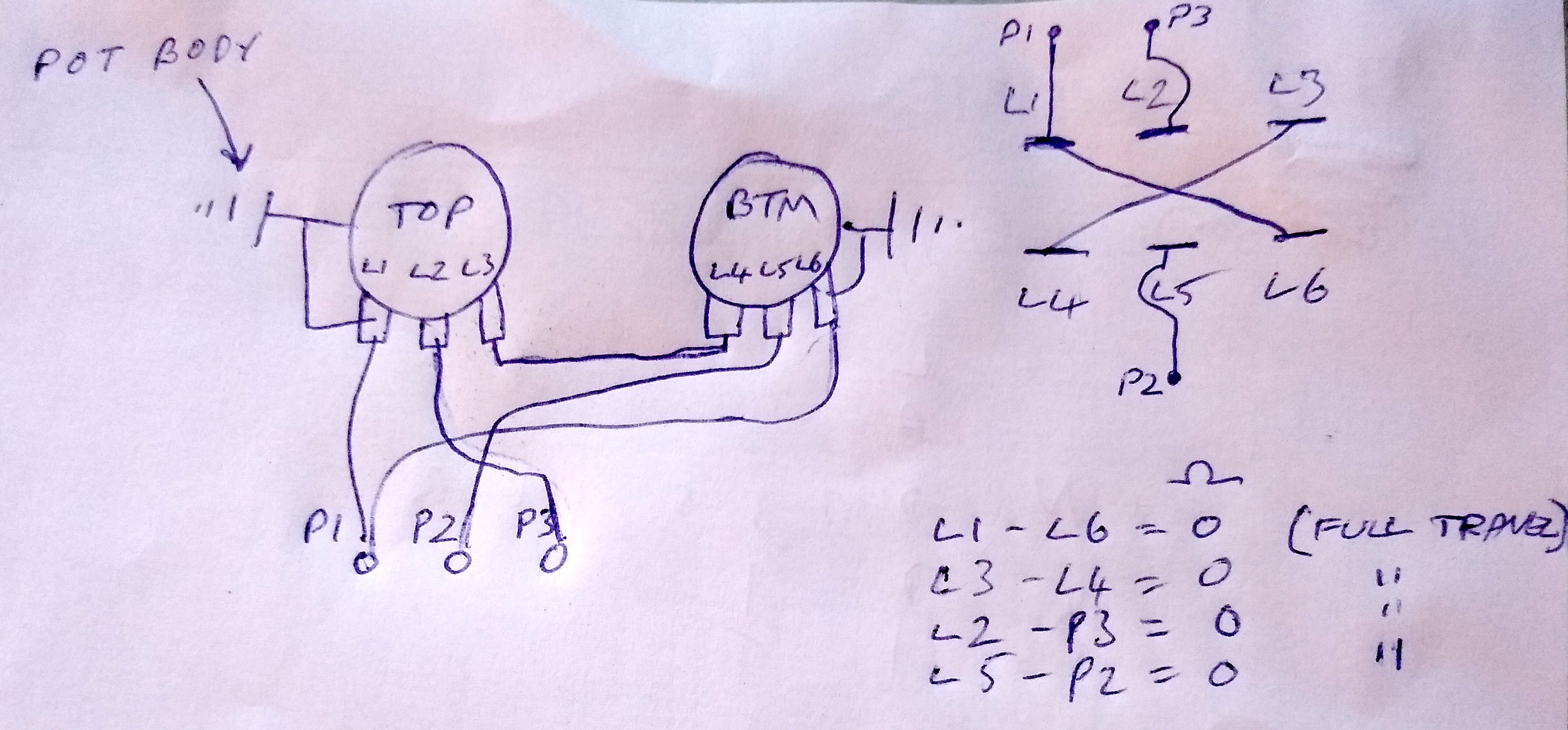
I took the back panel off and it was obvious that someone has had a go at the wiring to the blend pot. I originally thought the pot had only three lugs but upon closer inspection it does have six. The bottom row was hidden under the top row.
The way the connections have been made would appear to me to not allow panning between the two pickups, although I could be wrong.
Next to the blend pot are three electrical poles/posts. These may connect to the bottom three lugs but I can’t tell without removing the circuit board.
I ran a multimeter across the top three pot lugs (to where both pickup wires have been connected) while turning the control. I also measured the resistances across the three posts, again turning the control.
The results can be found in the attached sketch. (The pickups are active and there is also a red wire running between each pickup wire and the circuit board but I left these off the sketch for clarity. Also, with the pot lug values for L1 to L2, there was a gradual rise in resistance from 0 to 2.5k to midway then the value stayed at 2.5k for the rest of the control travel. I did not repeat this procedure for every measurement - just recording the readings at the three points on the pot travel A, B & C. Actually, I think I may have the decimal point in the wrong place throughout as the values should be more like 250k?).
I have also attached a photo of the circuit board.
I would greatly appreciate any advice as I am struggling to work out what I need to do, if anything, to get the blend pot working as it should.
I managed to find a photo of inside another MAB50. The circuit board appears to be identical to mine but the white pickup wires are running to the posts adjacent to the blending pot instead of being directly soldered onto the pot lugs.

The previous owner did say that he had had a problem with the electrics and that he had it repaired but didn’t tell me what the problem was.
However, I believe the that the blend control is not working as it should. Turning the control to one extreme has one pickup working only, middle has both pickups working and the other extreme also has both pickups working.
I posted this problem I was having in the other thread but thought I might be posting in the wrong place so I moved the continuation here.
Once again, and as stated in the other thread, I am a complete novice when it comes to guitars so apologies if I ask any stupid questions.
I took the back panel off and it was obvious that someone has had a go at the wiring to the blend pot. I originally thought the pot had only three lugs but upon closer inspection it does have six. The bottom row was hidden under the top row.
The way the connections have been made would appear to me to not allow panning between the two pickups, although I could be wrong.
Next to the blend pot are three electrical poles/posts. These may connect to the bottom three lugs but I can’t tell without removing the circuit board.
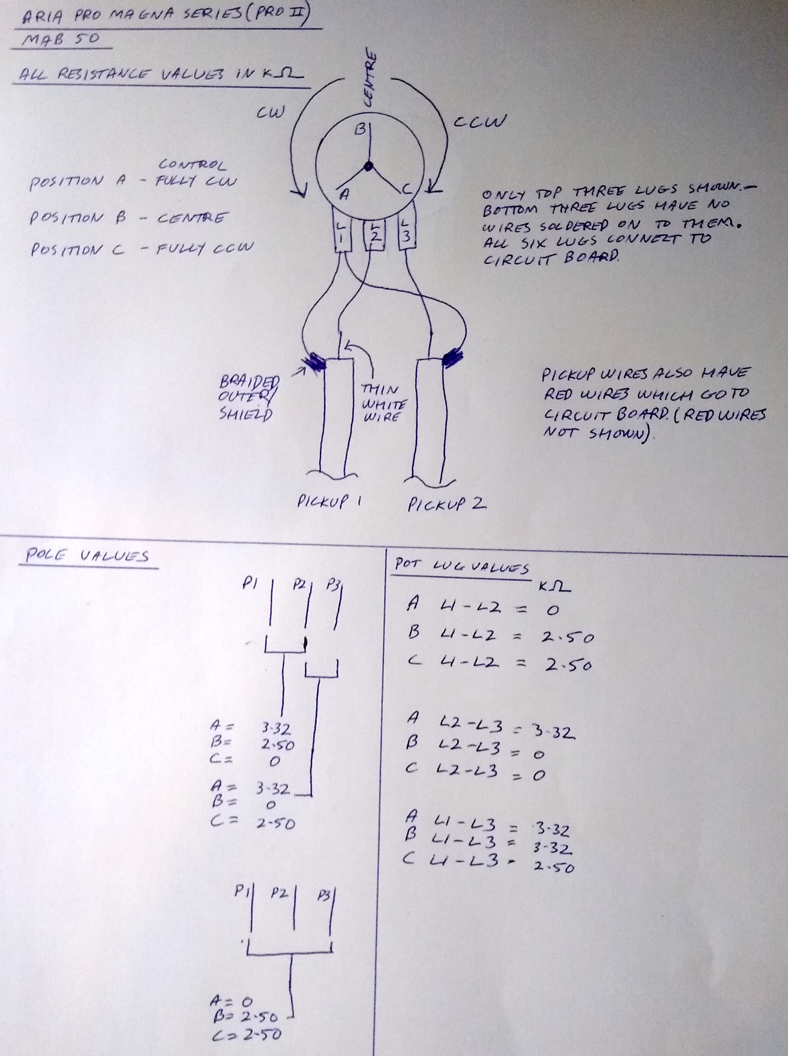
I ran a multimeter across the top three pot lugs (to where both pickup wires have been connected) while turning the control. I also measured the resistances across the three posts, again turning the control.
The results can be found in the attached sketch. (The pickups are active and there is also a red wire running between each pickup wire and the circuit board but I left these off the sketch for clarity. Also, with the pot lug values for L1 to L2, there was a gradual rise in resistance from 0 to 2.5k to midway then the value stayed at 2.5k for the rest of the control travel. I did not repeat this procedure for every measurement - just recording the readings at the three points on the pot travel A, B & C. Actually, I think I may have the decimal point in the wrong place throughout as the values should be more like 250k?).
I have also attached a photo of the circuit board.
I would greatly appreciate any advice as I am struggling to work out what I need to do, if anything, to get the blend pot working as it should.
I managed to find a photo of inside another MAB50. The circuit board appears to be identical to mine but the white pickup wires are running to the posts adjacent to the blending pot instead of being directly soldered onto the pot lugs.