• TalkBass has been independent since 1998. Add your voice.
    Create a free account to reply to discussions, view embedded media, and browse with fewer display ads.
    Join freeLog in
    Want zero display ads or expanded classifieds tools? Compare plans.

Build: OpAmpBuffer

Apr 5, 2011
1,287
630
CO
lERKCux.gif

This version was a mod to a different version. If I ever get around to updating it, I'll make the footprint much smaller.
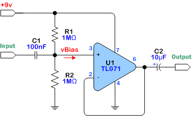

I'm paranoid of the capacitance and tone suck of me >25' cable, passive instruments, and signal chain.

Found this little guy through browsing and slapped it onto a digital perfboard (care to proofread the schematic-to-board conversion, in case I missed something?). I'll be ordering a plastic enclosure and having it attach to the strap of whatever passive instrument I'm using.

High input/low output impedance is the way to go and that's provided by this type of opamp configuration, right? Comments and critiques are greatly appreciated. I'll post progress as I build.


PzZ0O1a.png

PASSIVE>---6"--->BUFFER>-----Like a billion feet of cable----->SIGNALCHAIN>--->AMP

 
You shouldn’t leave the unused amp’s input terminals floating.

Why not use a low current single channel op-amp? It could be much more efficient depending on the op-amp chosen.

-Frank

Design called for TL072, which I happen to have about two dozen of; I don't have any single channel ICs on hand. I have almost all parts on hand, save for the case and 1/4" jacks.

Opens up the question of current draw, considering this will be on battery power. I'll look into that, although this project isn't entirely critical.
 
for the unused amp, most people tie the input of it (pin 5) to ground and short the output and - (pins 6&7).
Does that reduce current draw?

Updated to show single and dual opamp designs, and shorted amp pins. Left the IC model out, so that the builder can design to taste.

I'll be looking to balance power efficiency and sound transparency. There's a lot of debate over that.
 
Terminating the inputs as John said will prevent the unused op-amp from oscillating which can eat A LOT of current. And because the two op-amps are in the same package and use common power connections, there is a problem with channel crosstalk if one is oscillating.

Even with the unused op-amp terminated properly it is still burning battery current. A 072 has approx. 1.5 – 2.5mA idle per amp. A 062 has approx 200 – 250uA idle per amp.

You are building a very simple unity-gain buffer, so I wouldn’t worry too much about transparency. Most modern op-amps have distortion numbers that are difficult to measure.

-Frank
 
Terminating the inputs as John said will prevent the unused op-amp from oscillating which can eat A LOT of current. And because the two op-amps are in the same package and use common power connections, there is a problem with channel crosstalk if one is oscillating.

Even with the unused op-amp terminated properly it is still burning battery current. A 072 has approx. 1.5 – 2.5mA idle per amp. A 062 has approx 200 – 250uA idle per amp.

You are building a very simple unity-gain buffer, so I wouldn’t worry too much about transparency. Most modern op-amps have distortion numbers that are difficult to measure.

-Frank

That's good to know. I was just reading into the data sheet, and it lists current per amp. May as well save on batteries. I can afford to buy a few single opamps.

(TB is pretty rad in that I can pose questions and occasionally get responses from industry professionals, like the Designer/Owner of FEA Labs. Thanks!)
 
NkNEDFx.jpg


DPDT switch to save battery and bypass the circuit. Momentary button to short the signal to ground; kill switch, if you will. Why not.

...guess I'll just hang out until the single opamps, enclosures, and 1/4" jacks show up...

:hmm:
 
So, I got this thing wired up and put in line.

It works, but does the opposite of what its intended to do: enhances tone suck and
i
have
no
idea
why
it's
not
workking
corrententaelkasdjlfkajerlaejdflakdjfadf.

Help.
 
100nF = 0.1uF


As drawn the input corner freq is 1.6Hz.


-Frank


Input and output grounds are connective negative terminal.

1.6Hz would seem acceptable, assuming it's passing everything above that.

I'm compulsive about LEDs: added a 1k resistor and orange 3mm before the +V input, just to show that it's on. Would that cause any adverse effect? I'd troubleshoot by taking that out, but I've put everything away for the night, and it's never been a problem in the past.
 
Input and output are grounded to negative terminal.

1.6Hz would seem acceptable, assuming it's passing everything above that.

It is 1.6Hz, so the cap is more than adequate.

Pins 1 & 5 on the 071 are for nulling offset, so make sure that they are left open. Also if you have a voltmeter you should read half of the battery voltage on pins 2, 3 and 6.

-Frank
 
Also, with your layout with the dual opamp you have the unused + input tied to battery ground. With the single supply it would be better to connect the + input (pin 5) of the unused opamp to Vbias (the junction of R1 and R2).

-Frank
 
It is 1.6Hz, so the cap is more than adequate.

Pins 1 & 5 on the 071 are for nulling offset, so make sure that they are left open. Also if you have a voltmeter you should read half of the battery voltage on pins 2, 3 and 6.

-Frank

Also, with your layout with the dual opamp you have the unused + input tied to battery ground. With the single supply it would be better to connect the + input (pin 5) of the unused opamp to Vbias (the junction of R1 and R2).

-Frank

For the sake of "I'm not actually building the dual opamp design" I'll omit them from the discussion.

I'll grab a multimeter and check back in.
 
Well now that I've had some time to look at it, my theory that I'm an idiot has been revalidated:
The dual opamp and single opamp circuits aren't the same; it's not as simple as removing half of the opamp from the circuit.

In other news: I plotted the single opamp circuit onto the board, making as few changes as possible so I only have to shuffle a few parts around. I'll check back in shortly.

**OP UPDATED**