• TalkBass has been independent since 1998. Add your voice.
    Create a free account to reply to discussions, view embedded media, and browse with fewer display ads.
    Join freeLog in
    Want zero display ads or expanded classifieds tools? Compare plans.

Change a pickup's resonant frequency and tone with a loading capacitor

@micguy, roughly how many such shorted turns, around an average J pickup for example, are required for a noticeable effect?

That depends on the wire gauge, and how resonant the circuit is to begin with. With 22 gauge wire, I'll usually use at least 2. And they work better close to the windings - I'd put them under the pickup cover, but you might want to put some tape between the windings and the shorted turns to protect the windings. That said, i haven't done this in a while - most of my basses, I'm looking for a decent amount of resonance, so I don't typically do this, but in the past I have run into several occasions in guitars and basses where it was a useful tool. At my job (early in my career I designed phonograph cartridges), we used shorted turns made of specifically shaped brass pieces to tame things at high frequencies.

If you look at Bartolini's website, they mention using brass in their designs. As their pickups typically have fairly "tame" peaks/lots of eddy current losses (I've measured a bunch of them), I assume they are doing shorted turns (or some equivalent structure that adds eddy current losses) with that brass - there is really no other use for brass in a pickup that can't be done better by another material, so by default I think that's what they're doing with that brass.
 
  • Like
Reactions: LetItGrowTone
This is very closely related to the idea in another thread of a metal plate around the pickup, like a thick metal pickguard or just a section of one, but that thread was about noise reduction.
When they cut through the plate, so that it didn't make a circuit around the pickup, it stopped the noise reduction.
 
Last edited:
This is very closely related to the idea in another thread of a metal plate around the pickup, like a thick metal pickguard or just a section of one, but that thread was about noise reduction.
When they cut through the plate, so that it didn't make a circuit around the pickup, it stopped the noise reduction.

When I have shielded cavities around pickups, I will make a small cut somewhere in the shielding on one side - to avoid making a full shorted turn. You can get decent shielding with that small cut, but the eddy current losses are greatly reduced. If you look at Filtertron pickups, you will see a cut in the middle of the shield that is there for that reason. Gibson uses a metal that isn't highly conductive for their Les Paul and similar pickups, to keep eddy current losses from being too big.
 
  • Like
Reactions: LetItGrowTone
This is very closely related to the idea in another thread of a metal plate around the pickup, like a thick metal pickguard or just a section of one, but that thread was about noise reduction.
When they cut through the plate, so that it didn't make a circuit around the pickup, it stopped the noise reduction.

A conductive metal plate around a single coil pickup (as cited in that thread) can reduce electrostatic buzz somewhat (it is electrostatic shielding albeit not a full Faraday cage), but it does nothing for electromagnetic hum - to fix that that requires a hum cancelling architecture. And you should be able to make a cut (strategically placed - you gotta know what you're doing) to reduce eddy current losses, without affecting the shielding.
 
I like a lot of clarity and focus in my tone and use clear-sounding amps and cabs to benefit from that clarity, focus, and even dispersion on stage.
But I get annoyed when things are too edgy - so this thread has been a goldmine of great information.

My office was closed for the holiday yesterday - and I used the time off to do some electronics work on my basses; I worked with each bass to shape the tonality of the pickups with various caps, and the results have been pretty fantastic.

Bass #1 - Dingwall Z2 converted to Z3
This bass started life as a Z2 with a pair of Bartolini soapbars back by the bridge.
I added a Dingwall P-Tone pickup and always has trouble getting its output and voice to match the Bartolinis - so I replaced the Bartolinis with a pair of Nordstrand Big Blades, and the match was much better - but the P-Tone was still sounding a bit too bright in comparison. A 560pF loading cap on the P-Tone fixed it, and improved the blended tones.

Bass #2 - FrankenP with flats
I added a 1200pF cap to the Aguilar DCB to roll off the highs without sounding as muffled as the tone knob; it really gave it a warmer vintage flavor.

Bass #3 - Squire P-Bass modded to double-reverse P
This bass didn't actually need a coupling cap! But I've never been happy with how the two pickups blended.
I read (possibly here, possibly in another thread) that just like speaker crossovers, inline capacitors inject phase-shift into a signal, so I wired a .05uF cap in series with the neck pickup and now the pickups combine much better.

Bass #4 - active PJ
I've owned this bass for over 35 years, and with a 1-piece maple body, ebony fretboard and active EMG pickups it's always been REALLY bright.
Because the EMGs are active, the buffering makes the pickups immune to capacitive loading.
So the capacitors I added aren't technically loading caps - they are treble-cut caps - but they still helped a lot!
As is normal with active circuits: smaller pot + larger cap.
In this case, I used a .01uF cap on the neck pickup and a .022 uF cap on the bridge pickup, which tamed the crazy high-end of those EMGs.

Bass #5 - Yamaha BB300
I've cycled through 4 different pickups in this bass, and the Wilde P-46 has been the best match.
The bass seemed a little "middy" - so last week, I installed a Wilde Q-Filter.
But I found that when I cut mids, the resulting tone sounded too bright.
Once again, I added a coupling cap (820pF, IIRC) to get a nice, clear-but-smooth starting point for my tone.

Although it was a day to trying things out with alligator clips, careful listening, and lots of soldering - my total parts cost was probably less than a large coffee, and all of my basses sound better than ever!

Bottom line - if you're playing an electric bass, there is a LOT that can be done with dirt-cheap passive components.
 
my total parts cost was probably less than a large coffee, and all of my basses sound better than ever!
The cool thing about loading caps is that, when you add one, or change the value of one, you know what direction things will go, and if you don't like it....you're out half a buck or so. With a pickup swap (it's not an upgrade unless you like it better!), it's $100, and you have no idea if it will be better, worse, or about the same.
 
  • Like
Reactions: Das Jugghead
If I understand correctly, loading caps installed across the volume pot’s input and ground terminals both minimize volume differences when switching from parallel/series/single modes AND shift the frequency response curve meaningfully. Is that a correct interpretation?

In his sticky, Micguy wrote: I do this kind of thing in my basses all the time, and it works very well - multiple sounds, all with the same level. If you like the sound of your bass in both modes, all you need to do is, instead of switching the pickup from parallel to series, use a switch to add a capacitor to the circuit, but leave the bass wired parallel. Since the impedance of your pickup goes up by a factor of 4 when you put it in series, what you need to do is increase the capacitive load by a factor of 4.

I ask:
  • Do you permanently wire your twin PU basses in parallel and add one (or more switchable) loading caps across the volume pot to alter tone?​
  • Do you retain a tone pot?​
  • Re: P. Gagon’s 10/16 hand drawn “G&L Kiloton Bass” wiring diagram: With only the stock three-position switch and wiring configuration, is it possible to install a separate loading capacitor for each of the three PU configurations?​
I view the Kiloton as a two PU bass but with minimal distance between them which makes me wonder why. You don’t get the sonic differences delivered by two PUs separated by meaningfully different locations along the strings. You don’t get two convenient and different anchor points for your thumb. It seems like making a two PU bass and then removing the distance between them defeats a fundamental reason for implementing such a design!

If multiple tones are the goal, and if I understand Micguy’s explanations, wouldn’t it have been easier and more effective to use a single PU (or just one config of this one) and one or more switchable loading caps on the volume pot, with or without a tone control?

I ask because a Kiloton is my only base and it puzzles me. I removed the 0.047mf cap, tried a few replacements and settled on 0.1mf. The differences are more pronounced and I like it better but I’m still puzzled about the rationale for the PU design.

kiloton_wiring_diagram-1084861060.jpg
 
If I understand correctly, loading caps installed across the volume pot’s input and ground terminals both minimize volume differences when switching from parallel/series/single modes AND shift the frequency response curve meaningfully. Is that a correct interpretation?
Not quite. The point of using loading caps the way I do is that you get the same sounds that you would get from parallel or series connections without changing from parallel to series wiring, so the volume jump does not exist. You can also get sounds in between the sounds you would normally get from series or parallel connections, and/ or even deeper sounds than what a series connection gives you, just by using different loading capacitors.

In the case of a pickup that obtains it's hum cancelling by using two coils that listen to all the strings (each string is being picked up by two coils), there is an upper mid dip (which is at a different frequency on each string). That upper mid dip will be at the same frequency regardless of whether the pickup is wired in parallel or series, or wired in parallel and loaded capacitively - it's a physical wavelength effect, not an electrical phenomenon. That upper mid dip will not exist in a single coil wiring - changing the capacitive load will change the sound of the single coil mode, but it will not add or subtract an upper mid dip. In short, you can make a parallel connection sound like a series connection with capacitive loading, but you can't make a single coil sound like either of the dual coil modes, or vice versa.

For a pickup that listens to each string at only one point (a single coil pickup, a stack, a sidewinder, or a split hum canceller like a split P or split J pickup), the upper mid dip does not exist. I don't use pickups that listen to the string at more than one point as they rob articulation (which I like), but in the case of your Kiloton example, that is a factor in the sound to consider.

You can load different modes in the Kiloton example differently, but the switch used will limit things a bit - you can probably load 2 modes as you like them, but the third mode (with the switch in the middle) will be loaded by what happens with the switch logic. Not sure if that's a shorting or non - shorting switch, that will determine the limits/tradeoff you will have.
 
Not quite. The point of using loading caps the way I do is that you get the same sounds that you would get from parallel or series connections without changing from parallel to series wiring, so the volume jump does not exist. You can also get sounds in between the sounds you would normally get from series or parallel connections, and/ or even deeper sounds than what a series connection gives you, just by using different loading capacitors.

In the case of a pickup that obtains it's hum cancelling by using two coils that listen to all the strings (each string is being picked up by two coils), there is an upper mid dip (which is at a different frequency on each string). That upper mid dip will be at the same frequency regardless of whether the pickup is wired in parallel or series, or wired in parallel and loaded capacitively - it's a physical wavelength effect, not an electrical phenomenon. That upper mid dip will not exist in a single coil wiring - changing the capacitive load will change the sound of the single coil mode, but it will not add or subtract an upper mid dip. In short, you can make a parallel connection sound like a series connection with capacitive loading, but you can't make a single coil sound like either of the dual coil modes, or vice versa.

For a pickup that listens to each string at only one point (a single coil pickup, a stack, a sidewinder, or a split hum canceller like a split P or split J pickup), the upper mid dip does not exist. I don't use pickups that listen to the string at more than one point as they rob articulation (which I like), but in the case of your Kiloton example, that is a factor in the sound to consider.

You can load different modes in the Kiloton example differently, but the switch used will limit things a bit - you can probably load 2 modes as you like them, but the third mode (with the switch in the middle) will be loaded by what happens with the switch logic. Not sure if that's a shorting or non - shorting switch, that will determine the limits/tradeoff you will have.

So two devices are reacting to the same string, each generating its own representative signal, those signals are combined and by fluke of physics there's a small dip in the frequency response. Intuitively it's not surprising that the combination signal wouldn't be as articulate as the signal generated by only one PU element, at one point. That's kind of deflating, regardless of my ears, particularly when starting to monkey around with the electronics. In this context what G&L passive 4-stringer would you pick as your only?
 
So two devices are reacting to the same string, each generating its own representative signal, those signals are combined and by fluke of physics there's a small dip in the frequency response. Intuitively it's not surprising that the combination signal wouldn't be as articulate as the signal generated by only one PU element, at one point. That's kind of deflating, regardless of my ears, particularly when starting to monkey around with the electronics. In this context what G&L passive 4-stringer would you pick as your only?
Although I reject the idea of "my only", if I were to adopt a G&L, it would likely be something like an SB-1. I did have a PJ with that pickup in it as the "P" (wired in parallel), and that part of it was great. I really never used the "J" pickup I had on that instrument, so an SB1 (which is just the part I liked about that bass) is something that I'd probably like.
 
Although I reject the idea of "my only", if I were to adopt a G&L, it would likely be something like an SB-1. I did have a PJ with that pickup in it as the "P" (wired in parallel), and that part of it was great. I really never used the "J" pickup I had on that instrument, so an SB1 (which is just the part I liked about that bass) is something that I'd probably like.
Thank you!

Your exception noted, if limited to a KT, how would you modify the circuitry?

My thinking: The tone pot with the 0.1mf capacitor meaningfully affects only the first 25% of tone pot of rotation. Outside of that range the tonal differences between the three configurations, adjusted for volume, goes from “pretty similar” to “they all sound the same”, dimed. The tonal difference between parallel and series modes in the first 25% rotation is worthwhile but single coil is pretty much like parallel; and I could live without it.

So, wire in parallel and re-purpose the switch for two caps at the volume pot. Keep the tone control? A “047” cap?

If I feel like an unnecessary purchase, how would you modify an SB-1? It’s funny you mention that bass; I’ve been thinking “simple” during my tone search and have been wondering about an LB-100 or SB-1; tried a friend’s LB with a Bartolini and if that had been mine instead of the KT I probably wouldn’t be looking, but at this point I prefer the KT neck and body (and the 0.1mf cap KT tone), and that points to the SB-1, or nothing.

There's friction to flipping a bass and without changing anything permanently I can find out if I'd like the parallel thing with a couple of caps; I think the decision will fall out of that. And it may be to simply enjoy what I have....but I'll probably at least mess with it bit more!
 
What range of caps would you suggest for experimenting with moving the frequency response curve around? It was ~1800 for leveling volume between PU modes; similar for this use? Similar for this? Hi/Lo?
Loading caps don't "level the volume between modes" - the point is, if you start with the pickup wired in parallel, a loading cap can give you the same sound as you're have with the pickup wired in series, but the level will be the same as a parallel wiring - indeed, with any reasonable value of loading cap, the low end and low mids stay at the same level - you just re-tune things above that frequency response wise. Loading caps don't change levels, they retune things at upper mid and treble frequencies.

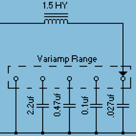
1800 pF is a suggested starting point for a loading cap - with typical cable values, and assuming some capacitance on board the pickups (the capacitance between windings contributes to loading the pickup), that loading will likely put you somewhere in the neighborhood sonically of a series connection. You can go up or down from there, depending on what you hear with that as a starting point. A decent set of capacitor values for a loading capacitor experimentation kit might be something like:

200 pF (smaller than this, you're not going to hear much change)
470pF
1000pf
1800pF
2700pf
3900pf
6800pF (you're not likely to want to go above this, but if you find you do want to go darker sounding, there is no risk in using higher values - nothing wil be harmed by more capacitance in the circuit.

You can parallel capacitors to get in between values - parallel capacitors add, so if you connect a 200pF and a 470pF in parallel, the resulting total capacitance is 670 pF.
 
Loading caps don't "level the volume between modes" - the point is, if you start with the pickup wired in parallel, a loading cap can give you the same sound as you're have with the pickup wired in series, but the level will be the same as a parallel wiring - indeed, with any reasonable value of loading cap, the low end and low mids stay at the same level - you just re-tune things above that frequency response wise. Loading caps don't change levels, they retune things at upper mid and treble frequencies.

1800 pF is a suggested starting point for a loading cap - with typical cable values, and assuming some capacitance on board the pickups (the capacitance between windings contributes to loading the pickup), that loading will likely put you somewhere in the neighborhood sonically of a series connection. You can go up or down from there, depending on what you hear with that as a starting point. A decent set of capacitor values for a loading capacitor experimentation kit might be something like:

200 pF (smaller than this, you're not going to hear much change)
470pF
1000pf
1800pF
2700pf
3900pf
6800pF (you're not likely to want to go above this, but if you find you do want to go darker sounding, there is no risk in using higher values - nothing wil be harmed by more capacitance in the circuit.

You can parallel capacitors to get in between values - parallel capacitors add, so if you connect a 200pF and a 470pF in parallel, the resulting total capacitance is 670 pF.
Thank you. I'll wrap up my order to Mouser, see where that takes me and report back after a while.
 
1764863542494.jpeg


I found a hex-coded rotary switch to be quite handy for experimenting, as it allows you to quickly switch between 16 different total capacitance values using only 4 capacitors. Each capacitor needs to be roughly double the value of the previous one - for example with the following:
- 330 pF
- 680 pF
- 1500 pF
- 3300 pF
you get a range from 330 pF up to 5810 pF (330 + 680 + 1500 + 3300)
 
View attachment 7381777

I found a hex-coded rotary switch to be quite handy for experimenting, as it allows you to quickly switch between 16 different total capacitance values using only 4 capacitors. Each capacitor needs to be roughly double the value of the previous one - for example with the following:
- 330 pF
- 680 pF
- 1500 pF
- 3300 pF
you get a range from 330 pF up to 5810 pF (330 + 680 + 1500 + 3300)
That's a good idea, I probably should have tried it but I was hoping to only do this once and didn't really want more stuff; alligator clip test leads.

It's on the bench with leads connected for a tone pot cap and also for a volume pot cap. I can see it's going to take a while to explore this tone forest but I have started.

I tried posting a photo but it failed; I'll try again later.
 
Last edited:
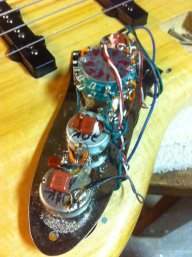
I monkeyed around with a 0.1uF cap across at least a half a dozen pairings between the volume and tone control pot lugs. Tone changes between the three pickup configurations were modest but what jumped out at me was that in all but one configuration (the original connection points per diagram posted above) the tone pot ceased to affect tone! I also tested a half dozen lower value capacitors installed as loading caps on the volume control and across each of the three PU configurations. I didn't make notes at that stage but tone alterations I perceived were insignificant.

I ended up going with 0.129uF in the original position on the tone pot with a 1Mohm resistor across its leads. Previously I'd been using a 0.1uF cap and no resistor. This configuration and both of those capacitors produce a much wider range of perceived tones between parallel, single, and series configuration than the original 0.047uF. They also cause the tone pot to provide considerably more tone adjustment than original.

All three configurations sound pretty close to indistinguishable with the tone control rotated 100% clockwise, adjusted for volume by ear. Between 0% and ~40% the total differences between the three configurations are quite distinct and the tone pot gives meaningful range in each. I'm very pleased with it. By the time you get to 50%, they're all starting to approach the same tonal zip code and by 100% I don't think I'd be able to tell the difference if blindfolded.

Unless I am very surprised when I get to do a side by side comparison between my Kiloton, an LB-100 and an SB-2 I think this tone-quest will be over. In any event, and to my ears, this configuration offers vastly more tonal options than as originally delivered from the factory and I am very happy with it; it really is a different animal now!
 
Last edited:
  • Like
Reactions: lark_z
I monkeyed around with a 0.1uF cap across at least a half a dozen pairings between the volume and tone control pot lugs. Tone changes between the three pickup configurations were modest but what jumped out at me was that in all but one configuration (the original connection points per diagram posted above) the tone pot ceased to affect tone! I also tested a half dozen lower value capacitors installed as loading caps on the volume control and across each of the three PU configurations. I didn't make notes at that stage but tone alterations I perceived were insignificant.

I ended up going with 0.129uF in the original position on the tone pot with a 1Mohm resistor across its leads. Previously I'd been using a 0.1uF cap and no resistor. This configuration and both of those capacitors produce a much wider range of perceived tones between parallel, single, and series configuration than the original 0.047uF. They also cause the tone pot to provide considerably more tone adjustment than original.

All three configurations sound pretty close to indistinguishable with the tone control rotated 100% clockwise, adjusted for volume by ear. Between 0% and ~40% the total differences between the three configurations are quite distinct and the tone pot gives meaningful range in each. I'm very pleased with it. By the time you get to 50%, they're all starting to approach the same tonal zip code and by 100% I don't think I'd be able to tell the difference if blindfolded.

Unless I am very surprised when I get to do a side by side comparison between my Kiloton, an LB-100 and an SB-2 I think this tone-quest will be over. In any event, and to my ears, this configuration offers vastly more tonal options than as originally delivered from the factory and I am very happy with it; it really is a different animal now!
From your description , you’re putting capacitors in a different position than where a loading cap would be. A loading cap does not take away the tone control’s function.

Your description of using a higher value in the normal tone cap position is spot on- at max tone there is no audible difference across a wide range of capacitor values. There’s a thread on how tone controls work (a sticky) that describes this (with response curves)