• TalkBass has been independent since 1998. Add your voice.
    Create a free account to reply to discussions, view embedded media, and browse with fewer display ads.
    Join freeLog in
    Want zero display ads or expanded classifieds tools? Compare plans.

Conspiracy to Commit Electronics Megathread

Oh...and a little something I've been working on to put into my next Bassdude build...
View attachment 7087519
Is that for a pre-gainstage like the Marshall JCM800 has ?
It makes me wonder with that 4PDT stomp switch.

I would also leave C6 the 100pF capacitor out or put it on a switch, that cap is the Bright capacitor and attenuates the bass frequencies.
You can see what it does if you put the values into the calculator on this page:
I freakin love the calculators on that website, I use it to alter all the caps in schematics to suit bass more if I need to.
Cheers
Mick
 
Last edited:
Is that for a pre-gainstage like the Marshall JCM800 has ?
It makes me wonder with that 4PDT stomp switch.

I would also leave C6 the 100pF capacitor out or put it on a switch, that cap is the Bright capacitor and attenuates the bass frequencies.
You can see what it does if you put the values into the calculator on this page:
I freakin love the calculators on that website, I use it to alter all the caps in schematics to suit bass more if I need to.
Cheers
Mick
Great advice as always Mick :)

With kids still at home, FT work, etc... designing/building is down-time for me... but I've been sick lately and sleeping worse than usual (you understand this more than I) and so I've had more time to design & learn TaydaToolbox/KiCad/Affinity Designer etc :)

Yes, that bright cap... I'll do an on/off comparison. With my prototype design, I can parallel the triodes of V1 and in this config. I've combined the signal after the bright cap.... but then I can't remove it (without a switch option) when I have the two V1 triodes in series... hmm...

In any case, I've attached a schematic of my high level design and of the PCB module as it stands...

To fit both footswitches, I'll need to cut the wings off the C2CE Bassdude board and shift it up in the pedal... [no easy tube swapping with this one]. This means R16, C8, R17, C9, and R14 have to be brought up to the mod board.
 

Attachments

Be very careful if you drill or cut any C2CE PCB's, I think many of them are 4 layer boards and you can't see what is on the internal layers.
I would ask Nathan first before cutting any of the PCB's, leave a picture showing where you want to make any cut or hole and he might check his layout for you to see if it is safe.
If you cut or nick any tracks the different layers might short out, there could be 240 volts difference between layers and when exposed by cutting a bit of the PCB you might get arcing between layers.
Normally the copper layers are a safe distance from the edges of the board, when you cut it you will expose the layers next to each other along the edge.
If I am repeating myself its because it might be a very unsafe thing to do.
It might be safer going up in size with the box to make everything fit.
 
  • Like
Reactions: WRM
Be very careful if you drill or cut any C2CE PCB's, I think many of them are 4 layer boards and you can't see what is on the internal layers.
I would ask Nathan first before cutting any of the PCB's, leave a picture showing where you want to make any cut or hole and he might check his layout for you to see if it is safe.
If you cut or nick any tracks the different layers might short out, there could be 240 volts difference between layers and when exposed by cutting a bit of the PCB you might get arcing between layers.
Normally the copper layers are a safe distance from the edges of the board, when you cut it you will expose the layers next to each other along the edge.
If I am repeating myself its because it might be a very unsafe thing to do.
It might be safer going up in size with the box to make everything fit.
As always, good advice and will do!
 
SamuelG
What program do you use to make artwork files for Tayda ?
I would love to find a free easy to use program but I have no idea what is needed.
If anyone knows of an easy to use and free program I would love to know what it is.
I have been using Affinity Designer 2.

It is a one time purchase vector design app for iPad. It was the most affordable/usable option I could find.

The support pages for the app are good and you can import the templates provided by Nathan and then go from there.
Be warned, even though the support is there, I have found this to be a very steep learning curve [Though I have never done anything like this before].

This page is very helpful: Tayda enclosure UV printing for guitar pedals
This has other important helps: Creating a PDF for Tayda UV Printing
For youtube: https://www.youtube.com/@scmglotr/search

Hope this helps get you started on this side of things.

Edit: Black Friday sales: iPad Graphic Design & Illustration Software | Black Friday 50% Off
 
Hi Nathan, @Sushi Box FX ,
I would like to do some mods to your beautiful Bassdude board to convert it into a double footswitch pedal in the same enclosure.
@Tassieviking raised the very real possibility that what I'm proposing could be dangerous, especially if there are high voltage lines in an internal layer that I cannot trace.
Would you mind confirming - or otherwise - that I am safe to make the following cuts to remove these wings from the board?
I am aware that these wings have a valuable structural role for tube swapping. My proposed mod will not be friendly for such endeavours.
1732955482764.png
 
  • Like
Reactions: Tassieviking
I have been using Affinity Designer 2.

It is a one time purchase vector design app for iPad. It was the most affordable/usable option I could find.

The support pages for the app are good and you can import the templates provided by Nathan and then go from there.
Be warned, even though the support is there, I have found this to be a very steep learning curve [Though I have never done anything like this before].

This page is very helpful: Tayda enclosure UV printing for guitar pedals
This has other important helps: Creating a PDF for Tayda UV Printing
For youtube: https://www.youtube.com/@scmglotr/search

Hope this helps get you started on this side of things.

Edit: Black Friday sales: iPad Graphic Design & Illustration Software | Black Friday 50% Off
Thanks for that, I bought the AD2 for half price, now I just have to figure it out.

Hi Nathan, @Sushi Box FX ,
I would like to do some mods to your beautiful Bassdude board to convert it into a double footswitch pedal in the same enclosure.
@Tassieviking raised the very real possibility that what I'm proposing could be dangerous, especially if there are high voltage lines in an internal layer that I cannot trace.
Would you mind confirming - or otherwise - that I am safe to make the following cuts to remove these wings from the board?
I am aware that these wings have a valuable structural role for tube swapping. My proposed mod will not be friendly for such endeavours.
View attachment 7089323
My main concern would be if there is a flood fill layer in there that will be exposed with trimming of the PCB
If layer 2 is flood filled with HV and layer 3 is flood filled with ground you might get some sparks when they are cut and exposed so close to each other along the edge.
 
  • Like
Reactions: SamuelG
SamuelG
What program do you use to make artwork files for Tayda ?
I would love to find a free easy to use program but I have no idea what is needed.
If anyone knows of an easy to use and free program I would love to know what it is.
I've used Inkscape for years. It's free and relatively simple to use. If you're doing something on the tricky side, there is almost always a YouTube tutorial available. Exports in multiple formats including Vector.

I've done artwork, drill templates, and larger panels with it. All went smoothly.
 
If you have a particular sized pedal/s you want to start with I can send you one or more of mine and you can mod/reverse engineer it if you wish?
I have a couple of 1590BB jobs I would like to make some artwork for, same spacing as the Bassdude except I have 6 pots so there is a pot in the middle of each row.
If you have a 1590BB picture I can start with I would appreciate it, thanks.
 
@Tassieviking Okay... so, I've attached an AD2 file. For it to attach in TB I had to add a .pdf extension on the end of the file, so you'll need to remove that :)

My AD2 projects tend to have 5 layers.
- Gloss-V [V for shiny, M for matte]
- Color
- Color Hardware
- White
- Background Colour.

Gloss-V...
- I tried for a full gloss cover over the top... this caused Tayda huge problems as they kept getting bubbles in the print and delayed my order by over a month. So from now on I'm only going to gloss over colours I want to pop.
- The gloss must be the Roland VersaWorks RDG_GLOSS colour. It appears a light teal colour on the design.

Color... spelt this way. This is the colour layer excluding white.

Color Hardware... this is my template layer for showing where my drill holes are placed.
- You will need to fix the placement of these holes as I have not made a standard layout design.

White... any colour you use will benefit from having an underlayer of white, especially on any dark enclosures.
- The white layer must be the Roland VersaWorks RDG_WHITE colour. It appears grey on the design.
- Once I have finalised the placement of a coloured design feature. I group/name it. Lock it. Then copy it to my white layer and change the colour to white so it sits directly underneath.

Background Colour.
- I set this to the colour of my enclosure so I can see how the colour scheme will likely look on the final product.

To export as a pdf to Tayda, you will need to exclude the "Color Hardware" and "Background Colour" layers while maintaining the order [and spelling?} of the remaining three layers.

Unfortunately, I changed my text to curves which means they cannot be edited as text. I won't do that on my next design.

On the bottom right of the AD2 screen there is a transform function.
- This is gold for placement/sizing of items.
- I anchor my selected item/group in the middle and then position using (x,y) co-ords.
- Note, Tayda has (0,0) at the middle of the board, while AD2 has (0,0) at the top left. So I take the Tayda Drill Template and use the following transform function (45+x, 57.75-y) [where 45 is half the enclosure width, and 57.75 half the height] to place my hardware.

Hope this helps :)
 

Attachments

  • Like
Reactions: darev and -Boscoe-
Thanks for that artwork for me to check out.
So I've had a reply from Nathan (thank you sir!) and yes there is high voltage present in the wings… hmm
What to do now?
Mount the stomp-switches and jacks in the box and see what it would look like if your pots grew really long legs, as in, PCB right at the back (bottom) of the box.
If there is enough room then you are very lucky.
Then cut the legs of some power diodes to extend the legs on the pots.

You could cut the PCB like you thought but you would need special varnish to paint the edges to help insulation on the edges
 
You might have to make a new PCB for tactile switches and buttons, it would have to sit very close to the front of the fascia to fit between the fascia and the Bassdute PCB
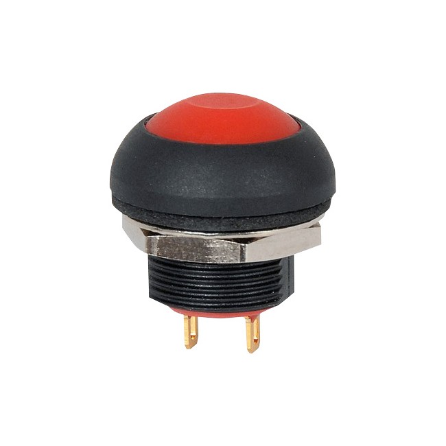
Tayda has 12mm buttons and possibly the right tactile switch needed.
You would have to have relays driven from the tactile switches.
Invalid Link Removed

Maybe a shallow switch with a separate relay board, you might have to use spacers to make the switch protrude a bit.
Invalid Link Removed

You could add a 1590A box to the 1590BB box and place the switches in there.
Or get one from Pedalnetics since he makes them already.

 
Last edited: