• TalkBass has been independent since 1998. Add your voice.
    Create a free account to reply to discussions, view embedded media, and browse with fewer display ads.
    Join freeLog in
    Want zero display ads or expanded classifieds tools? Compare plans.

Conspiracy to Commit Electronics Megathread

I know Nathan normally enjoys seeing his kits ‘in the wild’… but after seeing a messy ‘road-kill’ recently, I thought I’d present some ‘signs of life’ as well as give a shout out to one of Tassievikings MOD’s.
I’ve been using Tassieviking’s HPF mod on Nobelium builds. It’s super easy and very effective. The audible difference between off, 90Hz, and 45Hz (notional) is very clear.
I’d highly recommend it as it adds very little time to my builds.
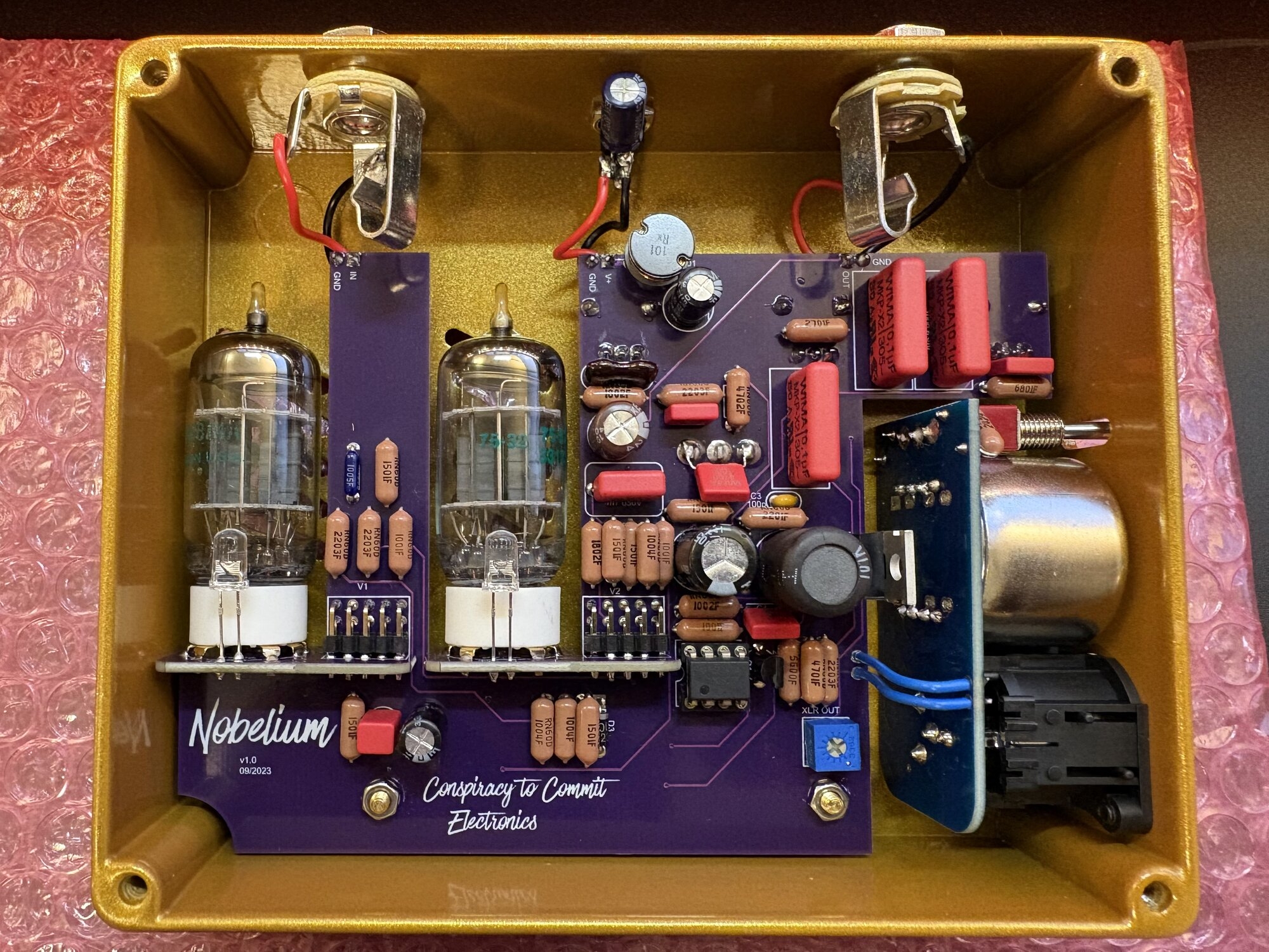
IMG_8436.jpeg

You can see the extra 4n7 red cap across pins 1 & 3 on the HPF on-off-on switch. What you can’t see is the cut trace between pins 2 & 3.
This is one of my Jensen DI builds.
 
I know Nathan normally enjoys seeing his kits ‘in the wild’… but after seeing a messy ‘road-kill’ recently, I thought I’d present some ‘signs of life’ as well as give a shout out to one of Tassievikings MOD’s.
I’ve been using Tassieviking’s HPF mod on Nobelium builds. It’s super easy and very effective. The audible difference between off, 90Hz, and 45Hz (notional) is very clear.
I’d highly recommend it as it adds very little time to my builds.
View attachment 7408029
You can see the extra 4n7 red cap across pins 1 & 3 on the HPF on-off-on switch. What you can’t see is the cut trace between pins 2 & 3.
This is one of my Jensen DI builds.
I never expected to feel the need to say "congratulations on correctly following the assembly instructions," but here we are. Thank you for sharing, this makes me feel much better. Do you find the inductor on the VIN makes a noticeable difference in noise rejection?
 
I’m mostly just enjoying going “over the top” with these builds. It costs me very little and I've found an easy way to add it to my build process. Using a CLC filter out front is very likely over-engineered, but might certainly help if people want to daisy chain the Nobelium with another pedal.
 
It certainly looks over the top but it looks beautiful and whoever gets that pedal will be very happy and lucky, that looks like Dale resistors and WIMA capacitors wherever they fit.
Some quick questions for you reverend, what type / brand of inductor did you use in there for the HV supply ?
Where do you source the components in general, I would love to see a BOM for your build.
Cheers
Mick
 
I have never seen CLC filters for pedals as a kit anywhere, perhaps it would be a good idea to make a pedal that has one input and several CLC outputs.
It would be easy and cheap to set up using an old laptop power supply into a 1590B box with LM78XX regulators and a CLC setup after that to an output, set the voltage you want for each output with a LM78XX and a laptop supply should be able to drive lots of C2CE pedals and the odd Sushi one as well.
I only own 2 Sushi pedals so far (Single Slice and PMLE) but I have my eye on a J C Emerald, I keep hesitating on the Emerald because I keep wondering if I should just build the real deal instead. I think a JCM 800 would look nice at my place but I hardly play at all. I guess I'm just a solder fumes sniffer junkie at heart.
 
  • Like
Reactions: BoobieMiles and WRM
Hey Tassieviking. Yes, Dale resistors, WIMA box film and Kemet electrolytic caps. I’ve had requests for premium & Jensen DI builds so I go over the top for fun. It also funds my solder fumes addiction as well. Some of the premium parts can be bought at Tayda (they’re getting in some WIMA caps etc but not many) for most of it I go to DigiKey. Regarding the HV inductor, I’ve got two left but then I’m changing it again. I’ve found a higher saturation current version that even fits in better. DigiKey product number: 732-4193-ND. It also has a lower DC impedance.
Send me a DM and I’ll see if I can get a BOM to you ;) .
Here is the front for some more eye candy.
IMG_8451.jpeg
 
I know Nathan normally enjoys seeing his kits ‘in the wild’… but after seeing a messy ‘road-kill’ recently, I thought I’d present some ‘signs of life’ as well as give a shout out to one of Tassievikings MOD’s.
I’ve been using Tassieviking’s HPF mod on Nobelium builds. It’s super easy and very effective. The audible difference between off, 90Hz, and 45Hz (notional) is very clear.
I’d highly recommend it as it adds very little time to my builds.
View attachment 7408029
You can see the extra 4n7 red cap across pins 1 & 3 on the HPF on-off-on switch. What you can’t see is the cut trace between pins 2 & 3.
This is one of my Jensen DI builds.

Looks very fancy and nice! - extra cap on the power Jack and inductor instead of the diode?
 
Looks very fancy and nice! - extra cap on the power Jack and inductor instead of the diode?
The diode is still there. I have the positive pin on the bottom and connect the diode from the positive up to the cap. Then I can run the leads as usual to the VIN. The inductor goes in the original diode slot with a little pin adjustment. I use two 220uF caps. I also have a 4.7uF ceramic cap (usually) under the second electrolytic cap for higher frequencies.
 
The diode is still there. I have the positive pin on the bottom and connect the diode from the positive up to the cap. Then I can run the leads as usual to the VIN. The inductor goes in the original diode slot with a little pin adjustment. I use two 220uF caps. I also have a 4.7uF ceramic cap (usually) under the second electrolytic cap for higher frequencies.
I’m guessing the idea to make the power supply cleaner in terms of hf stuff out of the audio band?
 
  • Like
Reactions: Tassieviking
Big thank you to Nathan who put some extra XLR daughter PCB's in my last order even though I had forgotten to add them to my shopping cart, I got a big surprise when I opened the package yesterday and found the extra PCB's placed in there.
Nathans memory is better then mine since it must be months since I asked if the new XLR PCB's for the Tungsten was going to be available separately for sale.
Thanks again Nathan.
Cheers
Mick
 
I see there is now fully built Lab Rats in the C2CE store, they look really nice and naturally nice and small as I'm sure they are made with SMD components and not TH like the PCB's are made for.
I am curious what the clipping diodes / LED's set up is in that pedal, I cant remember what I did in my first one but I have another PCB just waiting for me to build it.
I did make a change to the frequency in mine so it has a normal /dark / bass setting on it, it just needed one SPDT on-off-on switch and one cap and one resistor to make that change, here is the circuit I used in mine.
Lab Rat Bass Mod.png
 
  • Like
Reactions: SamuelG
I see there is now fully built Lab Rats in the C2CE store, they look really nice and naturally nice and small as I'm sure they are made with SMD components and not TH like the PCB's are made for.
I am curious what the clipping diodes / LED's set up is in that pedal, I cant remember what I did in my first one but I have another PCB just waiting for me to build it.
I did make a change to the frequency in mine so it has a normal /dark / bass setting on it, it just needed one SPDT on-off-on switch and one cap and one resistor to make that change, here is the circuit I used in mine.
View attachment 7447082
Stock (1N4148), Turbo (Red LEDs), and Raw (opamp only)

IMG_20260219_131837.png