• TalkBass has been independent since 1998. Add your voice.
    Create a free account to reply to discussions, view embedded media, and browse with fewer display ads.
    Join freeLog in
    Want zero display ads or expanded classifieds tools? Compare plans.

DIY - 212 cabinet - help with ports calculation

While you are optimizing the two/four internal braces, they'd be more effective if they centered between the baffle ports. Your baffle is weakest between the ports, where you only have a couple inches of section, thats where the bending will occur. But not sure you won't interfere with the driver magnets though, looks to fall on the same plane.
 
And what's going on in the area behind the ports? It looks to me like the bracing is forming resonant cavities separate from the main chamber...kind of like a band-pass enclosure. Is that part of the intent of the design?
I see now that changed somewhat in the updated design...for the better, I would think.

I've used some telescoping duct tubes similar to what you're showing, and they're great for fine tuning, but once I've determined the final length, I replace them with a single piece of tubing of the same diameter. Otherwise, you need to be really thorough cementing the two sections together...they'll want to rattle.
 
Over here, we use T-nuts with threaded fasteners if we don't use plain old wood screws. Regardless, you need a fastener every 100-125mm or so.

And what's going on in the area behind the ports? It looks to me like the bracing is forming resonant cavities separate from the main chamber...kind of like a band-pass enclosure. Is that part of the intent of the design?

Yes I have in mind T-nuts everywhere where it is possible to use.
No, it's no intent. Support was intended.
Maybe that design is better?

cavi.jpg


While you are optimizing the two/four internal braces, they'd be more effective if they centered between the baffle ports. Your baffle is weakest between the ports, where you only have a couple inches of section, thats where the bending will occur. But not sure you won't interfere with the driver magnets though, looks to fall on the same plane.

I'm not sure I got this. You mean these areas will bend, and I need support them?
And what will interface with magnets? ports are pvc
bending.jpg
 
I wouldn't mess around with bolts or screws, just glue the baffle in.

How do you plan on installing the grille? You might consider recessing the baffle to allow for a grille.
 
  • Like
Reactions: BasturdBlaster
Yes I have in mind T-nuts everywhere where it is possible to use.
No, it's no intent. Support was intended.
Maybe that design is better?

View attachment 3440402


I'm not sure I got this. You mean these areas will bend, and I need support them?
And what will interface with magnets? ports are pvc
View attachment 3440405

Think of the wood and structure as being soft, like rubber. Think about your driver, and think about pressing around the edge of each driver, like at the screws to see where the boundary is soft, softer, or ineffective. In your most recent sketch, you have good support around each driver on three sides. But one side, the side against the now-mostly-open internal baffle, is really soft, basically ineffective as a boundary support. You'll get some bending there. If you leave some baffle there, even just a couple inches, to couple the front with the back, it will eliminate this bending, and move the vibration mode much higher, where it doesn't matter for a bass cab.
 
Looks big. What do you think it will weigh?
I have in office Eden 212XLT and I hope my custom will weight the same, around 35kg. At home I have also 412 cab, (piece of trash on STX speakers, all 4 speakers forth at most 50 usd, I think it weights way more than 40kg) and I will be very happy if it will weight less.

Screenshot_1.jpg


I wouldn't mess around with bolts or screws, just glue the baffle in.

How do you plan on installing the grille? You might consider recessing the baffle to allow for a grille.

Yes I think at the end, I will glue baffle, will see. No grille, not many gigs, I would like to have nice looking cab in a room.
 
Maybe that design is better?
It certainly does address what I perceived might have been a problem...I'm not certain is would be too big of a deal, but I just thought it was beginning to look like a somewhat complex acoustic system. At any rate, you certainly seemed to have resolved it. The newer design wouldn't be as ridged as the previous one, but it should still be plenty sturdy...I kind of thought the first design looked like a bit of overkill. I'm presuming you're planning on using 19mm ply? And the overall dimensions are something like 75 H x 60 W ?

And I get that you're trying to make it with a removable baffle board, but unless you're planning to remove it dozens and dozens of times, threaded fasteners would be overkill...and IME, are somewhat difficult to get exactly right when working in plywood, even when just using T-nuts. One approach would be to use wood screws (and a gasket) until you're certain you have the final tweek done, and then glue it in. OR...you could split the baffle board into two sections, with only the part of it that carries the ports being removable. (Presuming adjustments to the ports is what's motivating the decision to employ a removable baffle board.) But a gasketed baffle board, secured by wood screws is a perfectly valid construction technique. I staple and glue my baffle boards in, but there have been times when I've regretted having done that...like when I wanted to change/upgrade the horn in a 2-way design.

Adding additional depth to accommodate a recessed grill is obviously a great recommendation...I kinda presumed you were going to do that anyway. Edit...just saw your latest post...so never mind on that. I'd at least put round, steel mesh grills over the drivers to protect them, but hey...to each his own.

What drawing program are you using? Your drawings are great...very lucid.
 
Yes I have in mind T-nuts everywhere where it is possible to use.
No, it's no intent. Support was intended.
Maybe that design is better?

View attachment 3440402


I'm not sure I got this. You mean these areas will bend, and I need support them?
And what will interface with magnets? ports are pvc
View attachment 3440405

Yes the baffle will flex. I think you should add posts from the back panel to the front baffle where your red Xs are. Your middle brace panel is better but should still have a center section (two big oval cut outs instead of one). As others agree I think you need to glue the baffle. All 12 seams should be glued for strength, and just as important, airtightness. All IMO of course.

Looks very nice BTW.
 
It certainly does address what I perceived might have been a problem...I'm not certain is would be too big of a deal, but I just thought it was beginning to look like a somewhat complex acoustic system. At any rate, you certainly seemed to have resolved it. The newer design wouldn't be as ridged as the previous one, but it should still be plenty sturdy...I kind of thought the first design looked like a bit of overkill. I'm presuming you're planning on using 19mm ply? And the overall dimensions are something like 75 H x 60 W ?

And I get that you're trying to make it with a removable baffle board, but unless you're planning to remove it dozens and dozens of times, threaded fasteners would be overkill...and IME, are somewhat difficult to get exactly right when working in plywood, even when just using T-nuts. One approach would be to use wood screws (and a gasket) until you're certain you have the final tweek done, and then glue it in. OR...you could split the baffle board into two sections, with only the part of it that carries the ports being removable. (Presuming adjustments to the ports is what's motivating the decision to employ a removable baffle board.) But a gasketed baffle board, secured by wood screws is a perfectly valid construction technique. I staple and glue my baffle boards in, but there have been times when I've regretted having done that...like when I wanted to change/upgrade the horn in a 2-way design.

Adding additional depth to accommodate a recessed grill is obviously a great recommendation...I kinda presumed you were going to do that anyway. Edit...just saw your latest post...so never mind on that. I'd at least put round, steel mesh grills over the drivers to protect them, but hey...to each his own.

What drawing program are you using? Your drawings are great...very lucid.

Thanks! Maya software. Overkill for design but that's only one software that I'm familiar.
Inside exacly 74x56x30. So 124L. At the end of design, I will reduce or add depth depending on tuning. I account 4L for drivers. I will have to also account damping materials.

I think everything would be much easier with 4 ports, I would be able to make support just like a cross, and everything would be still symmetrical. But I have problems with finding good ports and also I telescope ports are tempting.

18mm plywood plywood baltic birch
 
Last edited:
Yes the baffle will flex. I think you should add posts from the back panel to the front baffle where your red Xs are. Your middle brace panel is better but should still have a center section (two big oval cut outs instead of one). As others agree I think you need to glue the baffle. All 12 seams should be glued for strength, and just as important, airtightness. All IMO of course.

Looks very nice BTW.

support_2.jpg


Something like that? Back to front but with big hole, so avoiding resonant cavities.

Also I have questnio... crucial for design. How short that distance can be? Comparing to overal baffle depth. (between bass reflex end - rear panel)
 
Last edited:
Ok I will search how people deal with bending ports. Maybe hot air gun and slowly bend on a glass bottle?

If you want a beautiful cabinet, design a beautiful grille.
I will have that in mind. That's a beautiful grill but will not do a job..
grrrl.jpg


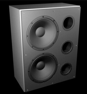
Here are some renders (forget about screws, I think I will keep them only temporary for tuning):
rt_1.jpg

rt_2.jpg
 

Attachments

  • rt_2.jpg
    rt_2.jpg
    21 KB · Views: 96
I play on signature marcus miller from 89, slap mostly. Fudging freeware means I should avoid and use other software?
Boxsim (which is published by Visaton) is a freeware that predicts more reliable numbers for port dimensions.
Boxsim can also predict shelf ports.

The Winisd predicted port dimension numbers for desired 55Hz tuning will actually bring you down to a (more realistic) ~50Hz magnitude of tuning.

I think 100 liters net volume is quite enough even for 5-string bass guitars.
Here you are with the port dimensions for (desired) 55Hz tuning.

Number of ports: 3
Diameter: 110mm
Length: 150mm

Fb: ~55Hz
F3: ~60Hz


Btw personally I'd design for two ports (D 110mm) rather than three ports which I regard as kinda "way overkill" for a MI bass cabinet.
For two ports D 110mm you want start with ~65mm port length which gives you Fb ~55Hz and F3 ~60Hz.
 
Boxsim (which is published by Visaton) is a freeware that predicts more reliable numbers for port dimensions.
Boxsim can also predict shelf ports.

The Winisd predicted port dimension numbers for desired 55Hz tuning will actually bring you down to a (more realistic) ~50Hz magnitude of tuning.

I think 100 liters net volume is quite enough even for 5-string bass guitars.
Here you are with the port dimensions for (desired) 55Hz tuning.

Number of ports: 3
Diameter: 110mm
Length: 150mm

Fb: ~55Hz
F3: ~60Hz


Btw personally I'd design for two ports (D 110mm) rather than three ports which I regard as kinda "way overkill" for a MI bass cabinet.
For two ports D 110mm you want start with ~65mm port length which gives you Fb ~55Hz and F3 ~60Hz.
Ok so having two ports I can make two separate baffles?
Also what about air velocity? For 2 ports WinISD shows 24 m/s quite a lot! That's why I would stay with 3 ports I think.

Also can I find somwhere BCH file for faital 12pr300 8hm?
 
Last edited: