• TalkBass has been independent since 1998. Add your voice.
    Create a free account to reply to discussions, view embedded media, and browse with fewer display ads.
    Join freeLog in
    Want zero display ads or expanded classifieds tools? Compare plans.

DIY Highpass filter issue

So I recently built up a little box implementing a Linkwitz-Riley 24dB high pass filter... and in testing I'm seeing something strange that I can't rightly explain.

Circuit is as follows:

1st order active highpass (7Hz) -> LR4 active highpass (60 Hz) -> 12dB gain stage -> variable attenuator

Everything looks great through the LR4 section - here is the signal at LR4 output:
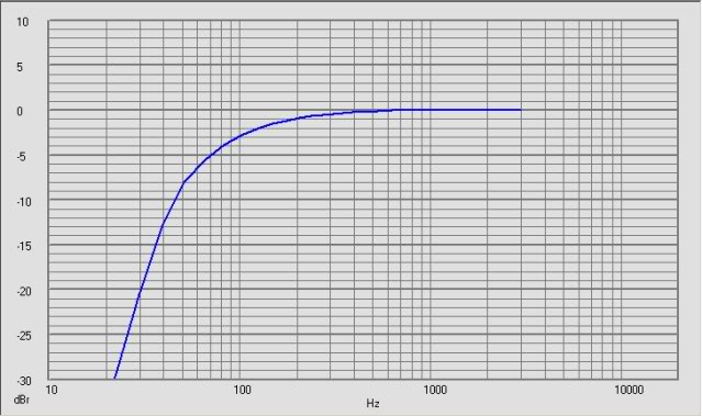
lfout.jpg


That output is feeding a gain/variable attenuation circuit:

circuit.jpg


Inverting amplifier should provide ~12dB gain (more accurately 11.7dB), and the attentuator should provide ~12dB attenuation (more accurately 14dB). Output of the gain opamp should be identical to output of LR24 section, just amplified 12dB.

...but it isn't. It looks like this:
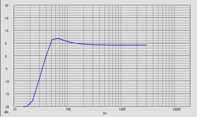
ampout.jpg


Op Amp is OP470 - 6MHz GBW, so it certainly is fast enough.

Test conditions are 50mV swept sine.
 
This circuit is the gain stage/variable attenuator.

It is following a standard Linkwitz-Riley 24dB octave highpass. It's a standard cascade of Sallen-Key topology implemented LR4.

Like the highpass section of this:

LR4.gif


That section of the circuit appears to be behaving beautifully. The gain stage/variable attenuator (in all too irritating contradiction with Spice simulation) on the other hand seems to be behaving badly.
 
Have you performed breadboarding yet... or is this second plot based on your simulators' guesstimate?

Both plots are actual measurements of the hand wired circuit - 50mV swept sine frequency response tests.

The first - good looking - plot is the measured frequency response 15-3000Hz at the output of the second stage of the LR4 filter.

The second - and ugly - plot is the measured frequency response 15-3000Hz at the output of the op amp inverting amplifier gain stage.

The whole thing looks wonderful in Spice - but they always do.

If the latter... which CAD tool are you using? Let me know... and, if we can't figure it out we'll forward it to someone else (e.g. Bob Pease).

Nah - I don't want to end up the butt of a joke in EDN... You never live down showing up negatively in Pease Porridge
 
Interesting... I'm real busy at the moment- but, let me study the facts and get back. By-the-way... Bob Pease is actually a wonderful guy to work with and treats you like family. I doubt he'd make an example of you, unless you request it.

You mentioned that "BB" vs. CAD disagrees... please include some more facts. Feel free to PM if you wish. The curve you posted has overshoot and may be clamping prior to achieving expected gain.

Regards,
Steve
 
throw a decoupling capacitor on the + of the opamp, and see how you go...suggest something like a 22uF.

You could also try a non-inverting gain stage.

also, since your using a double ended power supply, you may want to use a 1M pullup/1M pulldown on the gain-stage input to stabilize the signal.


Don't really know...but a little playing won't hurt.
 
throw a decoupling capacitor on the + of the opamp, and see how you go...suggest something like a 22uF.

It doesn't really seem to be showing what I would consider a normal behavior for an offset problem, and ground and power are strongly decoupled right near the power pins of the socket. I'd be more likely to throw in a resistor to prevent offset issues than a cap between the amp positive and ground.

You could also try a non-inverting gain stage.

I'm not sure what the idea there would be, other than the possibility that the op amp is behaving very oddly.

also, since your using a double ended power supply, you may want to use a 1M pullup/1M pulldown on the gain-stage input to stabilize the signal.


Don't really know...but a little playing won't hurt.

I could understand a pullup/down were operating anywhere near the rails - but I'm so far off...
 
You mentioned that "BB" vs. CAD disagrees... please include some more facts. Feel free to PM if you wish. The curve you posted has overshoot and may be clamping prior to achieving expected gain.

So here is the full story, for anyones edification -

A few weeks back I decided I wanted to throw together a high pass filter. I had a project box with +/-15V supplies, 1/4" IO, and a 14 pin DIP socket mounted on perfboard from a long ago project.

So I rummaged through my supply cabinet, found a likely quad op amp (OP470) and drew up a circuit in 5Spice (winspice engine).

Circuit is as follows:

input buffer (subsonic + DC blocking):
frontendcircuit.jpg


into LR4:
LR4circuit.jpg


feeding gain stage+variable attenuator:
gainstagecircuit.jpg


The circuit simulated nicely, so I wired/soldered it up and gave it a cursory check with the scope and signal generator. The sine wave coming out looked about like the one going in, so I took it home to play with.

It had more effect on the sound than I expected, so I wanted to see how it measured. Brought it back into work and ran frequency response tests... and saw the strange results.

At the LR4 stage output, things look OK:

LR4 out Spice sim:
LR4outsim.jpg


LR4 out measured:
LR4outmeasure.jpg


At the output of the gain op amp, things looked bad:

Gain out Spice sim:
gainstageoutsim.jpg


Gain out measured:
gainstagemeasure.jpg
 
it's strange how you are getting more boost on the low end like that. and when it interacts with the filter, you get almost a resonant peak @ 50-60 Hz...

what are you using for a power supply? If it's not battery powered, does your PS have any low-frequency noise, that's being falsely seen as signal?

also, try a small valued cap across the feedback resistor on the gain stage (R2).

Have you tried swapping out opamps, yet?
 
it's strange how you are getting more boost on the low end like that. and when it interacts with the filter, you get almost a resonant peak @ 50-60 Hz...

Yep - almost an overshoot looking response, but it's really just the odd frequency response of the gain section.

what are you using for a power supply? If it's not battery powered, does your PS have any low-frequency noise, that's being falsely seen as signal?

I was using a small DC/DC converter powered from a small wall wart, but I was suspicious of the power as being a problem - so today I hooked it up to a nice HP power supply capable of putting out 2 amps across +/-15V.

Sadly, no change. So now I'm thinking the PS isn't the problem.

also, try a small valued cap across the feedback resistor on the gain stage (R2).

Thought of that this afternoon - the signal looks good on the scope, but there could be some really high frequency hash there eating up bandwidth.


Have you tried swapping out opamps, yet?

No, and that is another thing I though of after leaving work... definitely something to try tomorrow.
 
Did you run a sweep with no input signal and the input shorted? That will give you the noise characteristic and it could tell you something about what's going on.

Good idea...

Out of curiosity, why are you using an inverting stage there

Ease of using the wiring that already existed, honestly.

and why do you have the pot right at the output instead of between the HPF output and the gain stage?

To keep signal levels higher - lowest levels anywhere in my circuit should be 0dB, if you put the pot before the gain stage the signal feeding the gain stage would be in the -12dB range.0